www.ti.com
IWR6843ISK / IWR6843ISK-ODS (deprecated)
65
SWRU546C–October 2018–Revised April 2020
Submit Documentation Feedback
Copyright © 2018–2020, Texas Instruments Incorporated
mmWaveICBoost and Antenna Module
5.6 IWR6843ISK Antenna
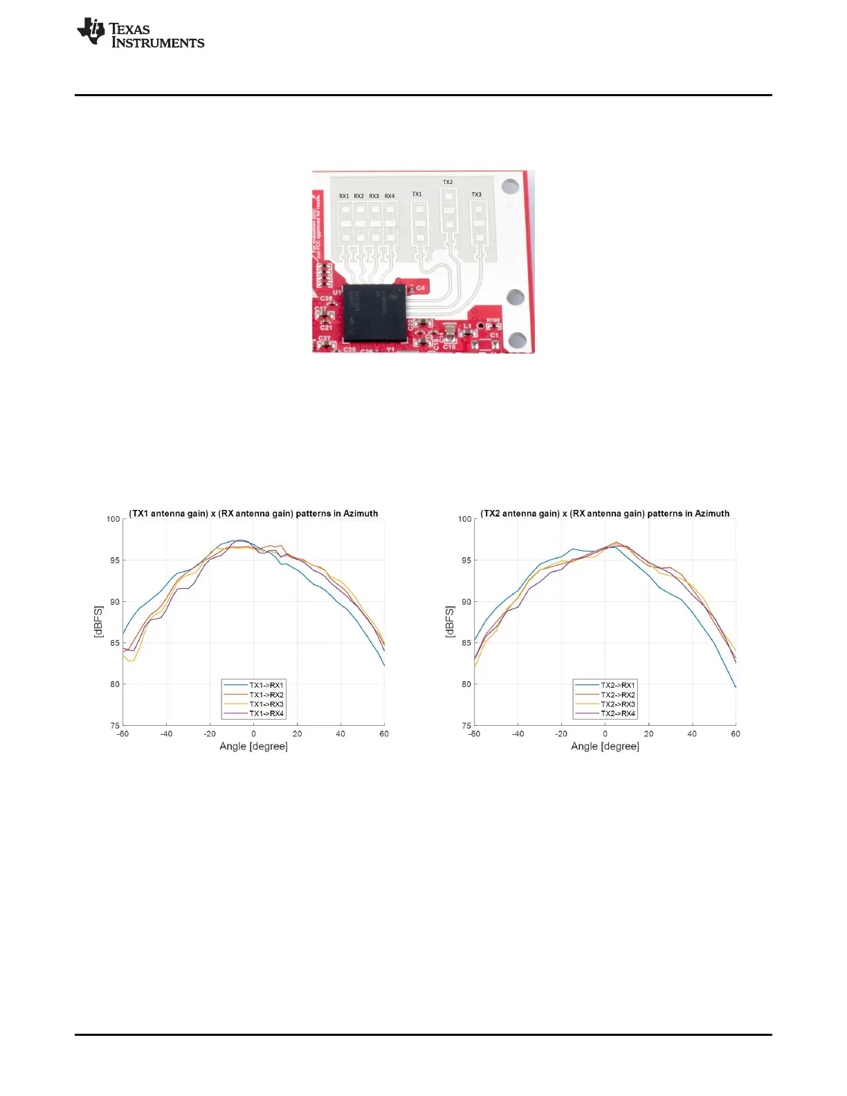
The IWR6843ISK includes onboard-etched long range antennas for the four receivers and three
transmitters. Figure 79 shows the PCB antennas.
Figure 79. PCB Antennas
Figure 80 through Figure 82 shows the antenna radiation pattern with regard to azimuth. Figure 83
through Figure 85 show the antenna radiation pattern with regard to elevation for TX1, TX2, and TX3.
All of the measurements were done with a Tx and Rx combination together. Thus, for the -6dB beam
width, you must see a -12db (Tx (-6dB) + Rx(-6dB)) number.
Figure 80. TX1 Antenna Radiation Pattern in Azimuth Figure 81. TX2 Antenna Radiation Pattern in Azimuth