IWR6843AOPEVM Rev F
www.ti.com
54
SWRU546C–October 2018–Revised April 2020
Submit Documentation Feedback
Copyright © 2018–2020, Texas Instruments Incorporated
mmWaveICBoost and Antenna Module
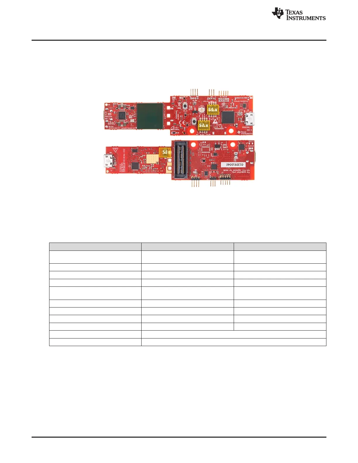
4.6 Switch Settings
Figure 67 shows the part designators and positions of the switches on the IWR6843AOPEVM.
Figure 67. IWR6843AOPEVM Switches
Table 21. Switches
Reference Designator Switch ON Switch OFF
S1.1 UART routed to 60-pin connector /
Bluetooth
UART routed to CP2105 UART
S1.2 UART routed to 60-pin connector UART routed to Bluetooth
S1.3 SOP0 pulled down SOP0 pulled up
S1.4 SOP1 pulled up SOP1 pulled down
S2.1 SPI MISO/MOSI routed to CAN
Transceiver
SPI MISO/MOSI routed to 60-pin
connector / BT/ LCD
S2.2 SPI CS routed to 60-pin connector SPI CS routed to BT/ LCD
S2.3 Bluetooth Enable Bluetooth Disable
S2.4 Not Connected Not Connected
S3 SOP2 Pulled up SOP2 Pulled down
SW2 Reset switch
SW3 User switch