www.ti.com
IWR6843AOPEVM Rev F
53
SWRU546C–October 2018–Revised April 2020
Submit Documentation Feedback
Copyright © 2018–2020, Texas Instruments Incorporated
mmWaveICBoost and Antenna Module
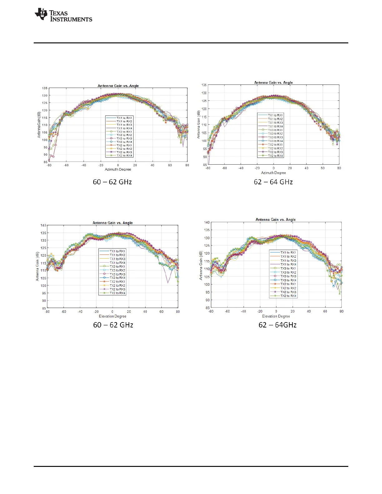
Figure 65 shows the antenna radiation pattern with regard to azimuth. Figure 66 shows the antenna
radiation pattern with regard to elevation for TX1, TX2, and TX3. Both show the radiation pattern for TX1,
TX2, and TX3 and RX1, RX2, RX3, and RX4 together.
Figure 65. Measured Azimuthal Radiation Pattern for All Tx to Rx Pairs (All 12 Virtual Antenna Pairs
Included)
Figure 66. Measured Elevation Radiation Pattern for All Tx to Rx Pairs (All 12 Virtual Antenna Pairs
Included)