MMWAVEICBOOST
www.ti.com
22
SWRU546C–October 2018–Revised April 2020
Submit Documentation Feedback
Copyright © 2018–2020, Texas Instruments Incorporated
mmWaveICBoost and Antenna Module
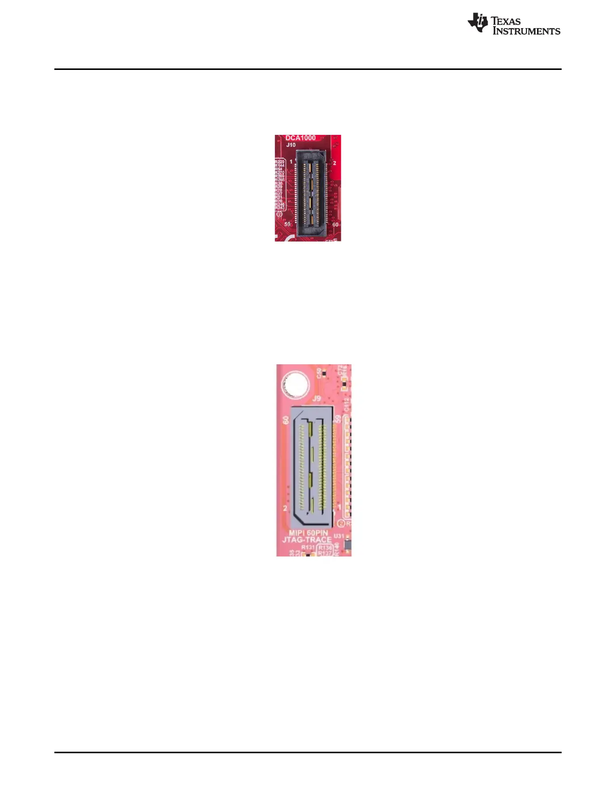
2.7.3 60-Pin High Density (HD) Connector (J10)
This connector enables interfacing of LVDS signals to the to the DCA1000 EVM for data capturing
purposes, as shown in Figure 19. DIP switch (S1) combinations must be set to ON/OFF, as mentioned in
Table 1, before interfacing to the DCA1000 EVM.
Figure 19. 60-Pin HD Connector (DCA1000)
2.7.4 MIPI 60-Pin Connector (J9)
This connector provides the standard MIPI 60-pin interface, as shown in Figure 20 for JTAG and trace
capability through emulators such as the XDS560pro. To use this interface, the JTAG lines from the
onboard emulator (XDS110) and 14-pin JTAG connector must be disconnected; this is done with S1 (12th
position of dip switch should be open), and the JTAG Debugger should not be connected on the 14-pin
connector.
Figure 20. 60-Pin MIPI Connector