MMWAVEICBOOST
www.ti.com
28
SWRU546C–October 2018–Revised April 2020
Submit Documentation Feedback
Copyright © 2018–2020, Texas Instruments Incorporated
mmWaveICBoost and Antenna Module
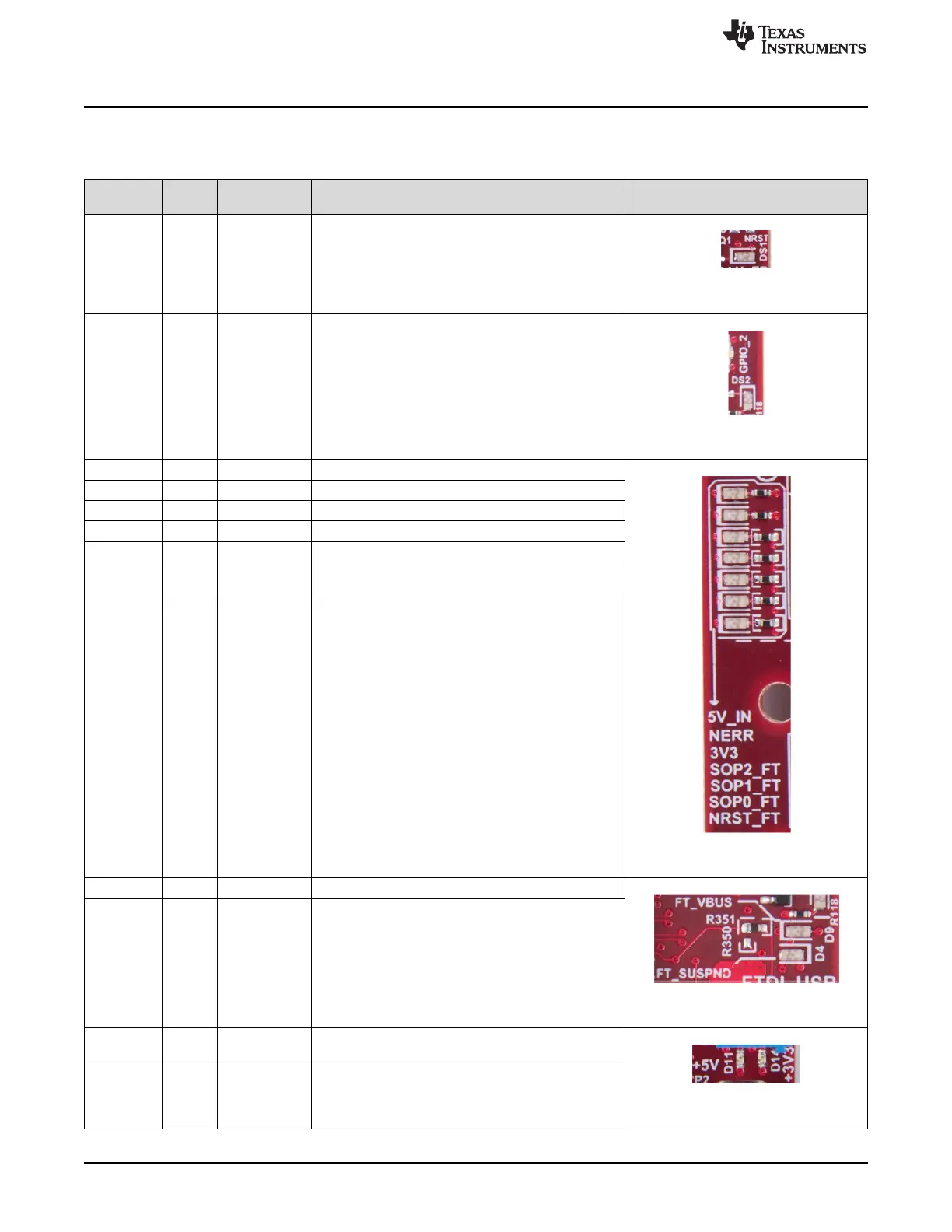
Table 15 provides the list of LEDs and usage.
Table 15. LEDs Information
Reference
Designator Color Usage Comments Image
DS1 Yellow nRESET
This LED is used to indicate the state of nRESET pin.
If this LED is glowing, the device is out of reset. This
LED will glow only after the 5-V supply is provided.
Figure 29. DS1
DS2 Yellow GPIO_2 Glows when the GPIO_2 is logic 1
Figure 30. DS2
DS3 Red NERROUT Glows if there is any HW error in the xWR device
Figure 31. LEDs
DS4 Red POWER This LED indicates the presence of the 5-V supply.
D5 Yellow SOR0 SOR0 (SOP2) state
D6 Yellow SOR1 SOR1 (SOP1) state
D7 Yellow SOR2 SOR2 (SOP0) state
D8 Red NRST
This LED is used to indicate the state of NRST pin. If
this LED is glowing, the device is in reset state.
D10 Red POWER 3V3 supply indication
D4 Yellow FTDI Glows if the USB is in suspend mode
Figure 32. D4 & D9
D9 Red POWER 5-V supply indication (from USB bus)
D11 Green POWER
5-V supply indication if the input voltage to board is
more than 5 V
Figure 33. D11 & D14
D14 Green POWER 3V3 supply indication