IWR6843AOPEVM (Deprecated)
www.ti.com
74
SWRU546C–October 2018–Revised April 2020
Submit Documentation Feedback
Copyright © 2018–2020, Texas Instruments Incorporated
mmWaveICBoost and Antenna Module
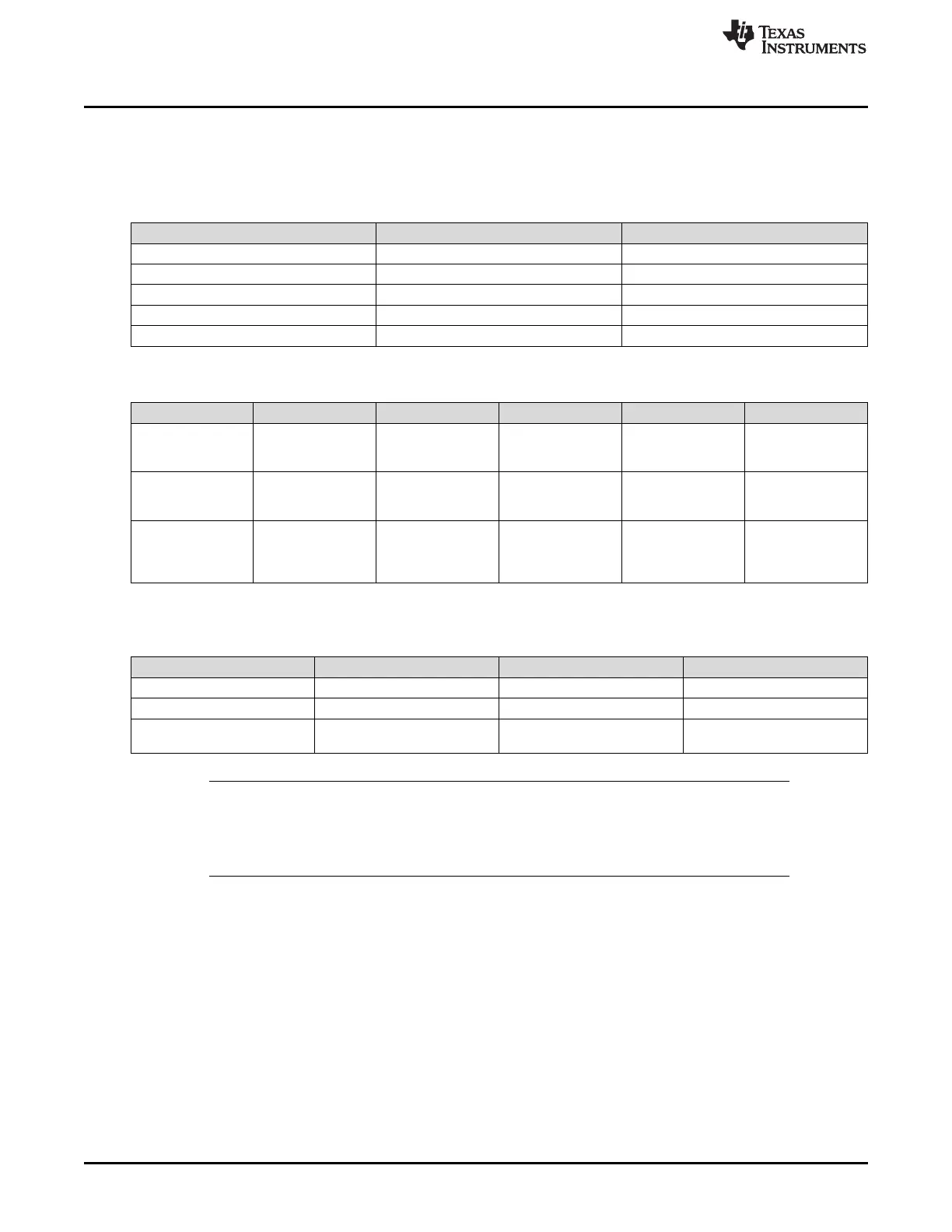
6.6 IWR6843AOPEVM Muxing Scheme
The IWR6843AOPEVM UART RX/TX can be routed to the Samtec 60-pin connector, USB to UART
(SICP2105), and bluetooth (BT) device (CC2640R2F), as detailed in Table 28 and Table 29.
Table 28. Pin Mux Settings I
Reference Designator Switch ON Switch OFF
S1 60-Pin Connector BT
S2 Disable 60-pin to BT Enable 60-pin to BT
S4 Breakaway UART Mainboard UART
S5 60-Pin Connector BT/LCD
S6 BT Enable BT Disable
Table 29. Pin Mux Settings II
S1 S2 S4 S5 S6
Modular Mode
SICP2015,. see
Figure 96
N/A ON OFF N/A N/A
Modular Mode -
CC2640R2F, see
Figure 97
OFF OFF ON OFF ON
MMWAVEICBOOST
- Samtec 60-Pin
Conn, see
Figure 98
ON ON ON ON OFF
6.6.1 SOP Configuration
SOP0(SW1
2
) SOP1(SW1
1
) SOp2(S3)
Flashing OFF OFF ON
Functional OFF OFF OFF
MMWAVEICBOOST Mode
(DCA1000, JTAG, and so forth)
ON OFF OFF
NOTE: SOP0 is set high when switch is on the OFF position and low when the switch is the ON
position. SOP 1 and 2 are set low when the switch is OFF and high when the switch is ON.
In mounted mode, the IWR6843AOPEVM is mounted on the MMWAVEICBOOST and the
SOP mode is set by the MMWAVEICBOOST.