www.ti.com
MMWAVEICBOOST
15
SWRU546C–October 2018–Revised April 2020
Submit Documentation Feedback
Copyright © 2018–2020, Texas Instruments Incorporated
mmWaveICBoost and Antenna Module
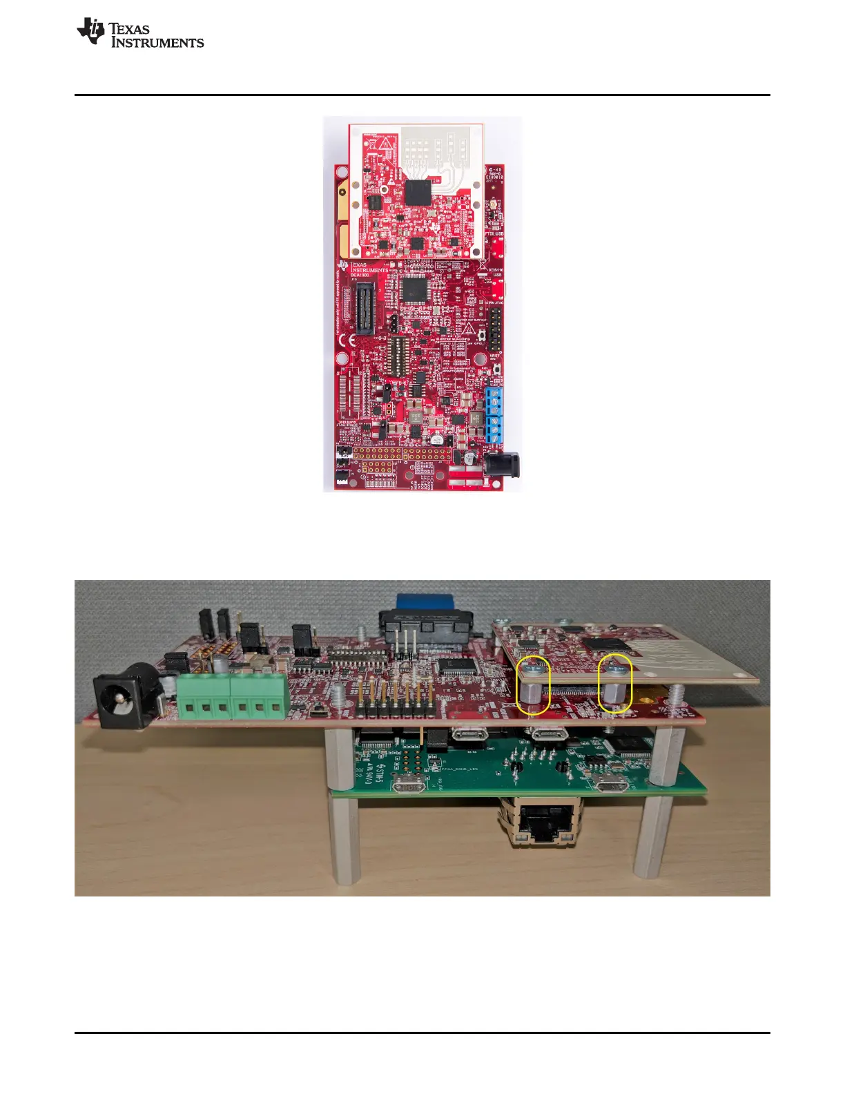
Figure 10. Integration of MMWAVEICBOOST and Starter Kit
Figure 11 shows the mechanical mounting of PCB. Spacers and screws can be used as heat sinking
elements to spread the heat from the starter kit to carrier board, as shown in Figure 11.
Figure 11. Mechanical Mounting of the PCB