CAUTION HOT SURFACE
CONTACT MAY CAUSE BURN
DO NOT TOUCH
www.ti.com
IWR6843AOPEVM (Deprecated)
69
SWRU546C–October 2018–Revised April 2020
Submit Documentation Feedback
Copyright © 2018–2020, Texas Instruments Incorporated
mmWaveICBoost and Antenna Module
6 IWR6843AOPEVM (Deprecated)
NOTE: RECOMMENDED DUTY CYCLE: The IWR6843AOPEVM operates at a maximum duty cycle
of 50%, running at a higher duty cycle increases the risk of damaging the EVM by exceeding
the maximum operating junction temperature (T
j
) of 105°C.
6.1 Hardware
The IWR6843AOPEVM includes four receivers and three transmitter wide field of antennas on the
package of the device. The IWR6843 operates at 4-Ghz bandwidth from 60 to 64 GHz, with a maximum
output power of 10 dBm; the IWR6843AOPEVM has an antenna gain of ~6 dBi.
NOTE: The IWR6843AOPEVM has been tested in the 60-64GHz band across the temperature
range of -20ºC to 60ºC.
NOTE: In accordance to the EN 62311 RF exposure test, a minimum separation distance of 20
centimeters should be maintained between the user and the EVM during operation.
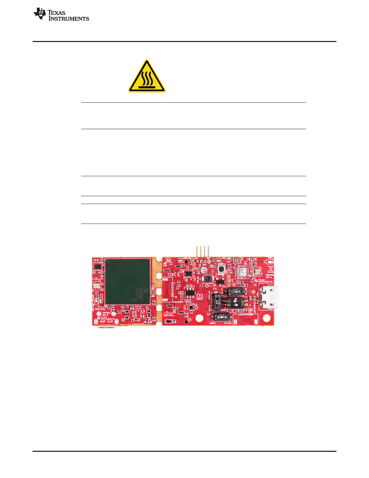
Figure 89. IWR6843AOPEVM Top View