CAUTION HOT SURFACE
CONTACT MAY CAUSE BURN
DO NOT TOUCH
www.ti.com
xWR6843ISK / IWR6843ISK-ODS REV C
29
SWRU546C–October 2018–Revised April 2020
Submit Documentation Feedback
Copyright © 2018–2020, Texas Instruments Incorporated
mmWaveICBoost and Antenna Module
3 xWR6843ISK / IWR6843ISK-ODS REV C
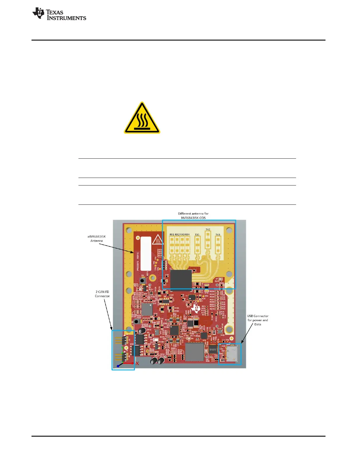
Figure 34 and Figure 35 shows the front and rear view of xWR6843ISK EVM, respectively. This EVM
includes onboard etched long range antennas for the four receivers and three transmitters. The xWR6843
operates at a 4-Ghz bandwidth from 60 to 64 GHz, with a maximum output power of 10 dBm; the
xWR6843ISK has an antenna gain of ~7 dBi and the IWR6843ISK-ODS has an antenna gain of ~5 dBi.
3.1 Hardware
3.1.1 xWR6843ISK EVM
NOTE: The xWR6843ISK has been tested in the 60-64GHz band across the temperature range of
-20ºC to 60ºC. The device is intended for use within the aforementioned limits.
NOTE: In accordance to the EN 62311 RF exposure test, a minimum separation distance of 20
centimeters should be maintained between the user and the EVM during operation.
Figure 34. xWR6843ISK Front View