www.ti.com
IWR6843AOPEVM Rev F
49
SWRU546C–October 2018–Revised April 2020
Submit Documentation Feedback
Copyright © 2018–2020, Texas Instruments Incorporated
mmWaveICBoost and Antenna Module
4.3 PCB Storage and Handling Recommendations
This EVM contains components that can potentially be damaged by electrostatic discharge. Always
transport and store the EVM in its supplied ESD bag when not in use. Handle using an antistatic
wristband. Operate on an antistatic work surface. For more information on proper handling, refer to
SSYA010A.
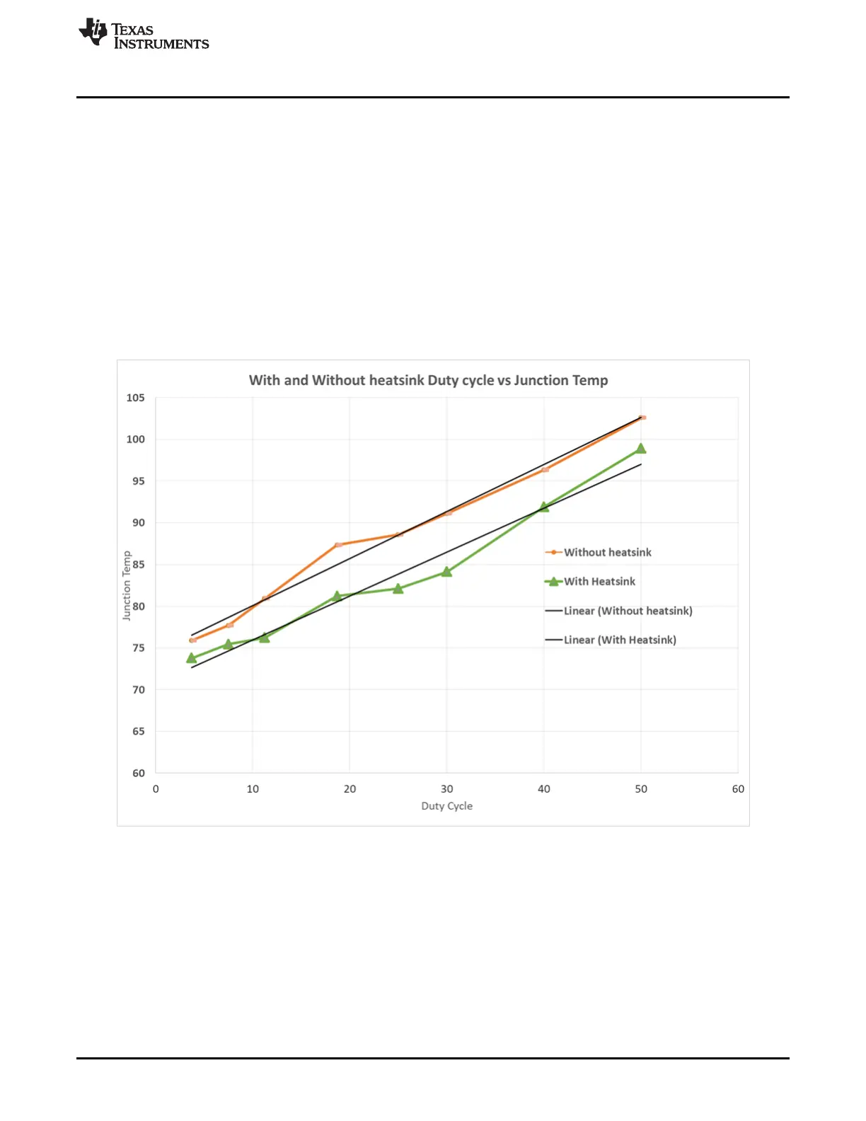
4.4 Heat Sink and Temperature
Users are strongly encouraged to use the IWR6843AOPEVM with the heat sink installed. Due to the
smaller size of the IWR6843AOPEVM, it is likely to get warmer than other larger sized EVMs on the
mmWave Radar portfolioso care must be taken to ensure the junction temperature does not exceed
105°C. Figure 60 shows measurement of junction temperature versus duty cycle taken with and without
the heat sink. As seen in the plot, the EVM can safely operate up to 50% duty cycle with or without the
heat sink. Although the heatsink is not absolutely required, usage of the heat sink provides protection
against exceeding the junction temperature at higher duty cyles.
Figure 60. Duty Cycle versus Junction Temperature
When using the EVM for custom applications, the duty cycle can be adjusted as needed, the heat sink
provided with the kit can be used, customers can also design their own heat sink using better heat
disippating materials or one with more surface area such as addition of fins. The CAD drawing for the heat
sink is shown in Figure 61