10-28 4157082 First Edition
ACCESSORIES
10
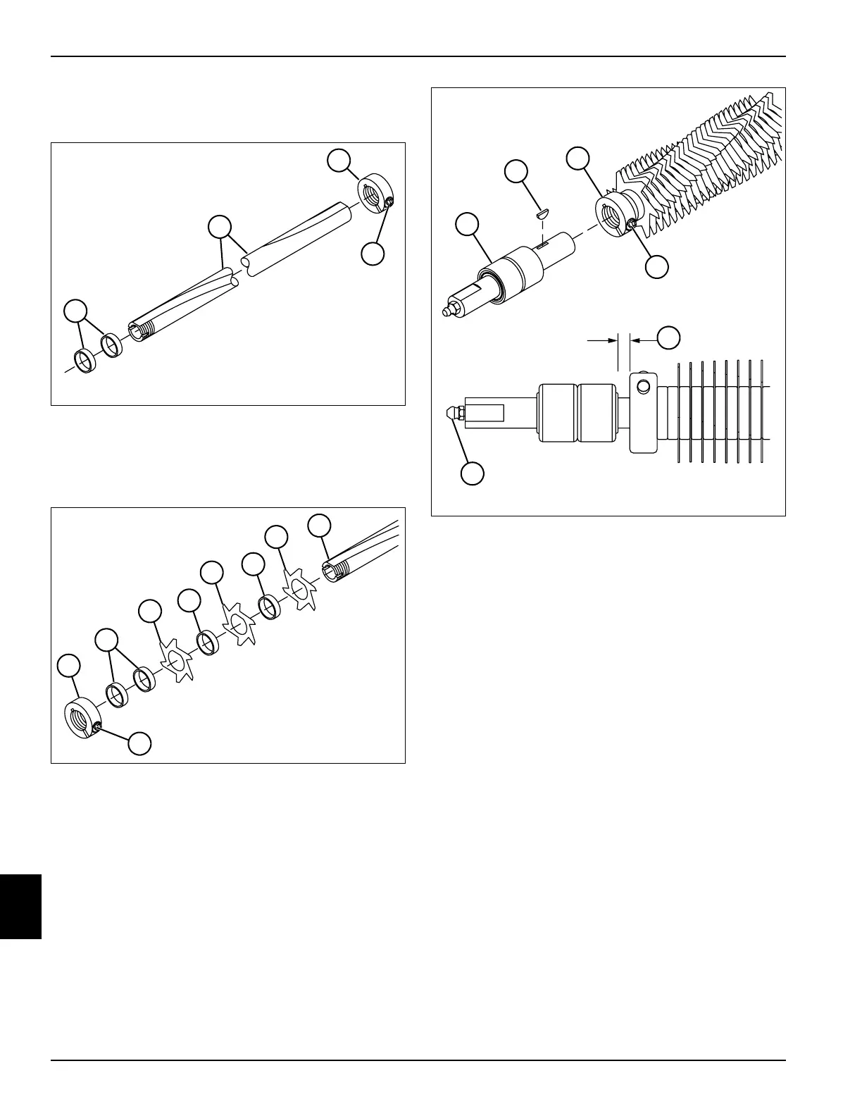
Assembly
See Figures 10-51 through 10-53.
Figure 10-51
1. Install locking collar (3) flush with the end of shaft (2).
Tighten set screw (4).
2. Install two spacers (1) on shaft (2).
Figure 10-52
3. Install blades (7) and spacers (8) on shaft (9).
4. Install two spacers (6) and locking collar (5) on shaft
(9). Do not tighten set screw (10) at this time.
Figure 10-53
5. Install key (12) in bearing shaft assembly (11). Install
shaft assembly (11) into the roller. Position the shaft
assembly so the distance between the face of the
locking collar and the bearing face (15) is the same
as noted during disassembly.
6. Tighten the set screw (14) in the locking collar (13).
7. Repeat steps 5 and 6 to install the bearing shaft
assembly in the other end of the shaft.
8. Apply NLGI Grade 2 grease to the grease fitting (16)
on both ends of the roller assembly.
TN0341
1
2
3
4
5
TN0340
6
7
8
7
8
7
9
10
11
TN0339, 0338
15
12
13
14
16