ix
CHAPTER 8 THEORY OF OPERATION..........................................................8-1
Electronics........................................................................................................................ 8-1
DC Power Supply................................................................................................. 8-1
Bias Power Supply............................................................................................... 8-1
Detector and Preamplifier .................................................................................... 8-2
Input Signal Conditioning Board ......................................................................... 8-2
Temperature Control Board ................................................................................. 8-3
The Microprocessor System................................................................................. 8-3
Display Module........................................................................................ 8-3
Processor Board ....................................................................................... 8-3
Analog to Digital Board........................................................................... 8-4
Digital/Analog Board............................................................................... 8-4
C-Link Board ........................................................................................... 8-4
Software ........................................................................................................................... 8-4
Subassemblies.................................................................................................................. 8-5
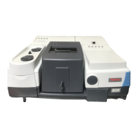
Optical Bench....................................................................................................... 8-5
Correlation Wheel and Chopper Motor ............................................................... 8-5
Infrared (IR) Source ............................................................................................. 8-5
Flow Components ................................................................................................ 8-6
Temperature and Pressure Transducer................................................................. 8-6
CHAPTER 9 OPTIONAL EQUIPMENT ............................................................9-1
Rack Mounts with Slides ................................................................................................. 9-1
Internal Zero/Span and Sample Solenoid Valves............................................................. 9-3
Zero/Span Check.................................................................................................. 9-3
Remote Activation of Zero/Span and Sample Valves ..................................................... 9-6
Input Pins ............................................................................................................. 9-7
Instrument Status Outputs.................................................................................... 9-7
4-20 mA Isolated Current Output .................................................................................... 9-9
Teflon
Particulate Filter.............................................................................................. 9-10
Purge Housing ............................................................................................................... 9-10
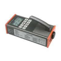
Instrument Handle.......................................................................................................... 9-12
APPENDIX A WARRANTY.............................................................................. A-1
APPENDIX B RS-232 COMMANDS................................................................ B-1