Chapter 2 Installation
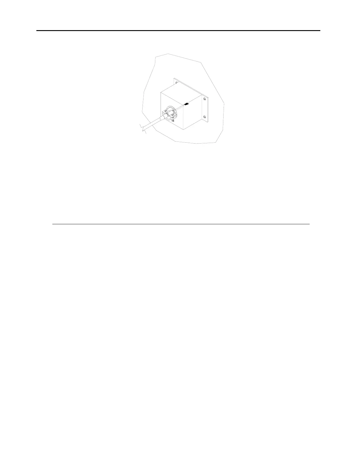
Figure 2-5.
Properly Installed Shield Cable
1. Install cable clamp into shield cover and secure. Be sure there is good electrical
conductivity between clamp and shield cover.
The following is a parts list of components in the analog output cover assembly:
Part No. Description Qty.
7592 Analog output cover 1
11519 8-Position header 2
5889 #6 Star lock washers 4
5820 6-32X3/8” screw 4
14549 Cable clamp 1
STARTUP
1. Turn the power on.
2. Set instrument parameters such as operating ranges and averaging times to
appropriate settings. For more information about instrument parameters, see
Chapter 3, “Operation.”
3. Before beginning actual monitoring, perform a multipoint calibration as described in
Chapter 4, “Calibration.”
2-6