Chapter 9 Optional Equipment
REMOTE ACTIVATION OF ZERO/SPAN AND SAMPLE VALVES
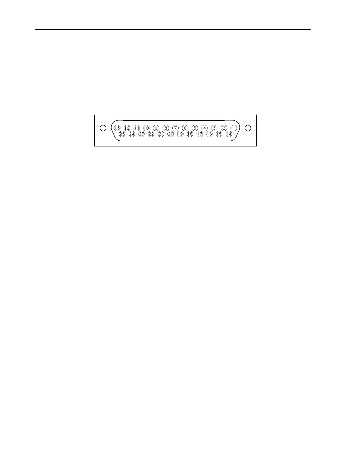
The rear panel I/O (DB25) connector, shown in Figure 9-3, enables the zero/span and
sample valves to be remotely controlled via contact closure. In addition, the connector
has several instrument status outputs. Option switch 1 must be on and option switch 2 off
in order to enable the remote I/O connector.
Pin Out
(1) Ground (13) NC
(2) NC (14) Ground
(3) NC (15) NC
(4) NC (16) NC
(5) INPUT - Zero Gas (17) NC
(6) Ground (18) INPUT - Span Gas
(7) Relay Common (19) Ground
(8) STATUS - Concentration Alarm (20) Relay Common
(9) STATUS - Local or Remote Mode (21) STATUS - Zero Mode
(10) STATUS - ppm or mg/m3 mode (22) STATUS - Span Mode
(11) STATUS - General Alarm (23) NC
(12) Relay Common (24) STATUS - NC
(25) Relay Common
Figure 9-3.
Rear Panel I/O Connector
64P947-5
9-6