Chapter 2 Installation
Analog Output Cover Installation
This analog output cover must be mounted over the analog outputs to comply with
89/336/EEC Directive. This procedure describes how to install the user-supplied analog
output cable in the instrument’s analog output cover. The following shielded cables or
their equivalent are recommended:
Cable Gauge No. of Conductors
Alpha #1741C 20 2
Alpha #1746C 18 2
Alpha #5320/2C
*
20 2
Alpha #51 52C
*
20 2
Alpha #5162C
*
18 2
Alpha #1743C 20 4
Alpha 1747/4C 18 4
Alpha #5320/4C 20 4
Alpha #5154C 20 4
Alpha #5164C 18 4
Belden #8208 18 2
* Maximum shielding. Under harsh environments, maximum shielding may be required.
The following tools are required:
Small
screwdriver
Wire stripper
Electrical tape or heat shrink tubing
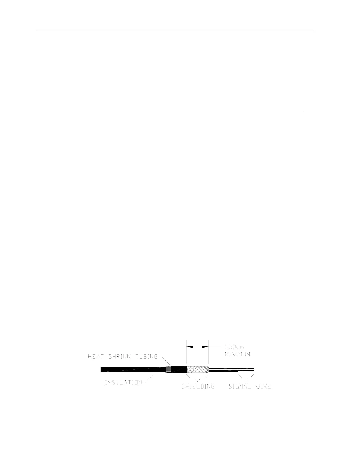
The user-supplied shielded analog output cable must be properly grounded
by coming
into full contact with the cable clamp (mounted to the analog output cover). To ensure
full contact, the shielding must be exposed and folded back over the cable as shown in
Figure 2-3.
Figure 2-3.
Shielded Cable with Shielding Pulled Back
2-4