Technical Support Bulletins
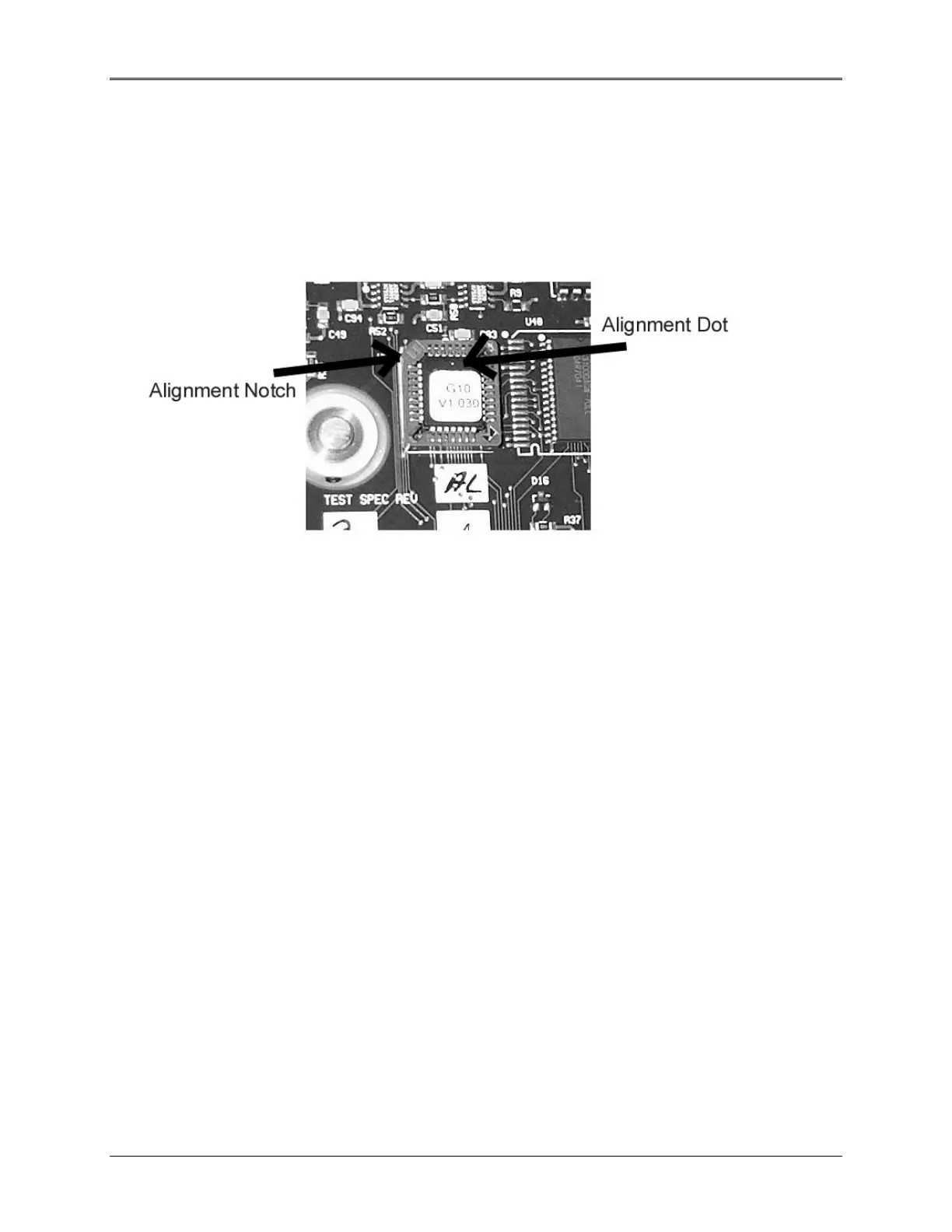
7. When installing the new ROM, take care to note the orientation of the notch and the “dot” on the
chip, and line them up with the notch in the socket and the dot printed on the Circuit board (see
Figure 11.1). Note that the label may be in any orientation- do not use the label to determine the
orientation of the IC.
8. After ensuring proper alignment, press the ROM gently into the socket and make certain that it is
fully seated.
Figure 11.1 Close-up photo of the socket and ROM
Caution: Improper insertion will damage the new ROM and possibly the instrument!
9. After installation is complete, replace and secure the bottom cover and turn the unit right-side-up.
10. Connect Power and turn on the instrument.
11. When prompted, press F1 or F2 (first or second unmarked key from the left [under the display])
for a UV or Visible-only model, respectively.
12. After the unit boots up, connect the instrument to a PC running the Spectronic GENESYS 10
Service Diagnostic application package (19200,N,8,1), and follow the calibration instructions in
the Service manual.
Note: You will need to re-enter the serial number into the instrument using the Service
Diagnostic application.
11-10
 Loading...


