Disassembly and Replacement
3. Remove the remaining two screws securing the Sample Detector cover.
4. Lift the Sample Detector cover off the base and set aside.
CAUTION: CIRCUIT BOARDS AND OTHER ELECTRONIC COMPONENTS ARE
SUBJECT TO DAMAGE FROM ELECTROSTATIC DISCHARGE. TO
PREVENT SUCH DAMAGE, USE A WRIST OR HEEL GROUNDING STRAP.
GROUND TOOLS THROUGH A CONDUCTIVE MAT BEFORE TOUCHING
ANY POTENTIALLY STATIC-SENSITIVE ASSEMBLIES OR DEVICES. WHEN
HANDLING PRINTED CIRCUIT BOARDS OR OTHER ELECTRONIC
ASSEMBLIES, HOLD THE BOARD BY ITS EDGES TO AVOID TOUCHING
CIRCUIT TRACES OR DEVICES WITH BARE HANDS OR FINGERS.
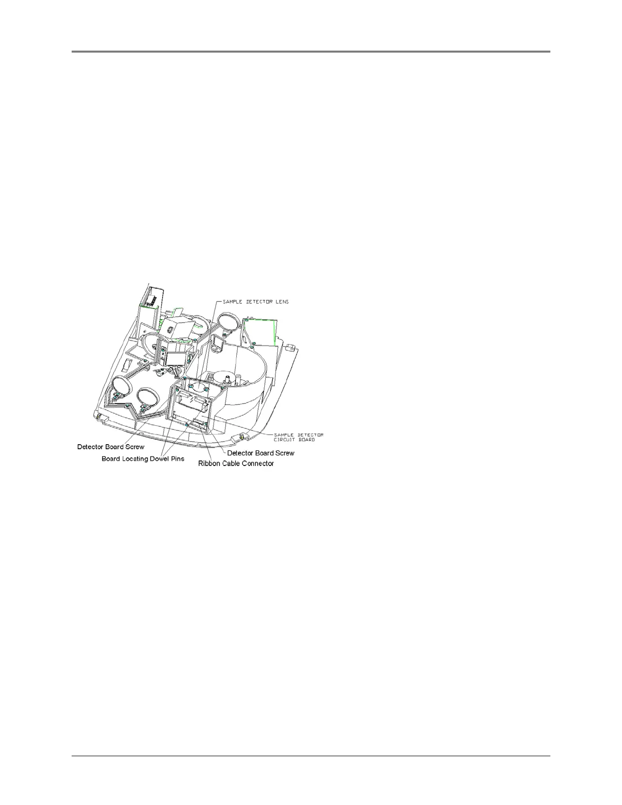
5. Remove the Sample Detector Circuit board (335901-6034 [UV] or 335901-6044 [Vis]).
Figure 5.11 Sample Detector
6. Remove the two screws securing the Sample Detector Circuit board to the base.
7. Carefully pull the Sample Detector Circuit board away from its locating dowel pins and remove it
from its mounting position.
8. Remove the ribbon cable from its connector on the Sample Detector Circuit board.
9. Remove the lens (335901-020S [Vis] or 335901-021S [UV]) if cleaning, or replacement is required.
10. Hold the lens with a lens tissue, soft cloth, or lab gloves and remove the two screws and washers
securing the lens.
11. Remove the lens and set aside.
CAUTION: NEVER TOUCH THE LENS WITH YOUR FINGERS. ALWAYS USE A LENS
TISSUE, OR SOFT COTTON CLOTH, OR CLEAN LAB GLOVES TO AVOID
OILS GETTING ONTO THE LENS.
5-11
 Loading...


