HYDRAULIC DRIVE SYSTEM
6-6 36” & 40” Toro GrandStand Service Manual
6
5. Place one friction composite washer and steel
washer onto the pivot bolt (Fig. 440).
6. Position the pump drive belt around the engine, idler
and pump pulleys (Fig. 442).
Fig. 440 DSCN-2795a
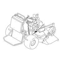
B. Secure the idler assembly with a nut (Fig. 441).
Fig. 441 DSCN-2799a
7. Install the extension spring from the idler bracket to
the spring anchor (Fig. 443).
Fig. 443 DSCN-2660a
A. Hydraulic pumps D. Clutch retainer
B. Idler pulley E. Pump drive belt
C. Clutch pulley F. Pump drive pulley
Fig. 442 g.67G012686
A
B
C
F
D
E

 Loading...

