HYDRAULIC DRIVE SYSTEM
6-26 36” & 40” Toro GrandStand Service Manual
6
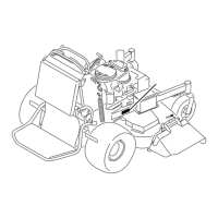
3. Secure the reservoir tank to the tank bracket using
the two sets of bolts, washers and nuts (Fig. 514).
6. Fillthereservoirtothe“COLD”uidlevelwiththe
speciedhydraulicuid.SeeyourOperator’sManual
forthespecieduid(Fig.517).
5. Securethereturnhosetothereturnttingusingthe
hose clamp (Fig. 516).
Fig. 514 DSCN-2890a
4. Installthesuctionhosetothesuctiontting(Fig.
515).
Fig. 515 DSCN-2887a
Fig. 516 DSCN-2906a
Fig. 517 g.71G012685
7. Purge the air from the hydraulic system. See
“Bleeding the Hydraulic System” on page 6-35.
A. Cap C. Colduidlevel-full
B. Bafe D. Hotuidlevel-full
A
D
C
B

 Loading...

