AWC7813 motion controller user manual
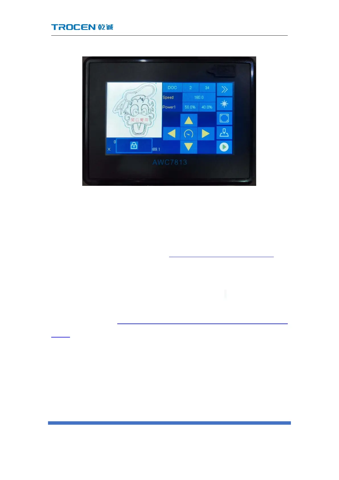
Figure3-5-1 Setting the lock screen
3.6 Coordinate display area
You can view the coordinate position of the laser head in the coordinate display
area, click this area to switch between the XY axis coordinates and the ZU axis
coordinates, for details, please refer to Figure3-1-3 Main interface area division. The
position of the machine zero is different, and the coordinate system is also different.
There are four coordinate systems with the machine zero at the upper left corner,
upper right corner, lower left corner, and lower right corner. According to different
coordinate systems to determine whether the graph is beyond the interface. For
details, please refer to 4.3 Why does the prompt "Beyond border limit! Continue?"
appear.
3.6.1 The coordinate system with the machine zero in the upper
left corner
When the machine zero (the machine limit position) is in the upper left corner,
the X-axis coordinate increases when the laser head moves to the right, and the