User's Guide _______________________________________________________________________
142 __________________________________________________________________ M211107EN-C
Light Receiver
The Light Receiver consists of a PIN photodiode, preamplifier, voltage to
frequency converter, backscatter measurement light source LED, and
some control and timing electronics.
The receiving PIN photodiode senses the transmitted light pulses
scattered from the aerosol particles. The signal voltage is filtered and
detected by a phase sensitive lock-in amplifier synchronized with the
transmitter.
An ambient light level as high as 30 kcd/m
2
does not influence the
detection of the photo diode, neither does it saturate the preamplifier. The
AMBL signal (proportional to the ambient light) is lead to the CPU for
monitoring.
Additional Measurements
PWD32 includes the RAINCAP
®
for estimating the water content of
precipitation, and the TS Temperature Sensor for measuring the sensor
cross arm temperature (TS). Both additional sensors are measured and
interfaced by the PWC12 board. The RAINCAP
®
temperature TDRD is
measured for the RAINCAP
®
heating (drying) control, and the box
(PWC12) temperature TB is measured for the box heating monitoring.
Vaisala RAINCAP
®
Rain Sensor
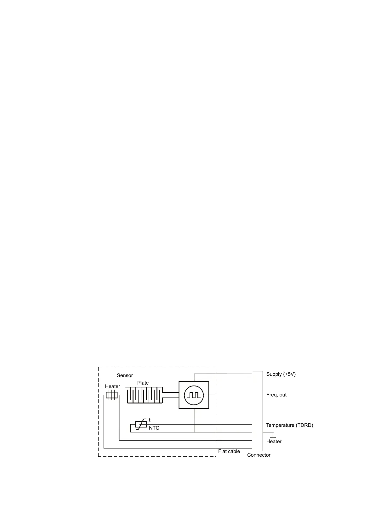
The RAINCAP
®
signal is proportional to the water amount on the
sensing surfaces. Water on RAINCAP
®
changes the capacitance of the
sensor elements. The capacitance of the elements determines the output
frequency of an oscillator.
The frequency signal is measured once a second. It is expressed in
internal units specific to PWD32. The DRY value is approximately 800,
which is also shown in the Status (STA) message.
0008-012
Figure 44 RAINCAP
®
Block Diagram
 Loading...


