Chapter 4 _______________________________________________________________ Installation
VAISALA ______________________________________________________________________ 141
To mount the measurement head cover, follow these instructions:
1. Place the ladder to the left and right sides of the instrument for best
access to the three lock screws at each side of the cover.
2. Lower the measurement head cover carefully on top of the support
unit whereas the six lock screws have to slide into the associated
gaps in the support unit.
3. The six lock screws have to be fastened one by one as follows:
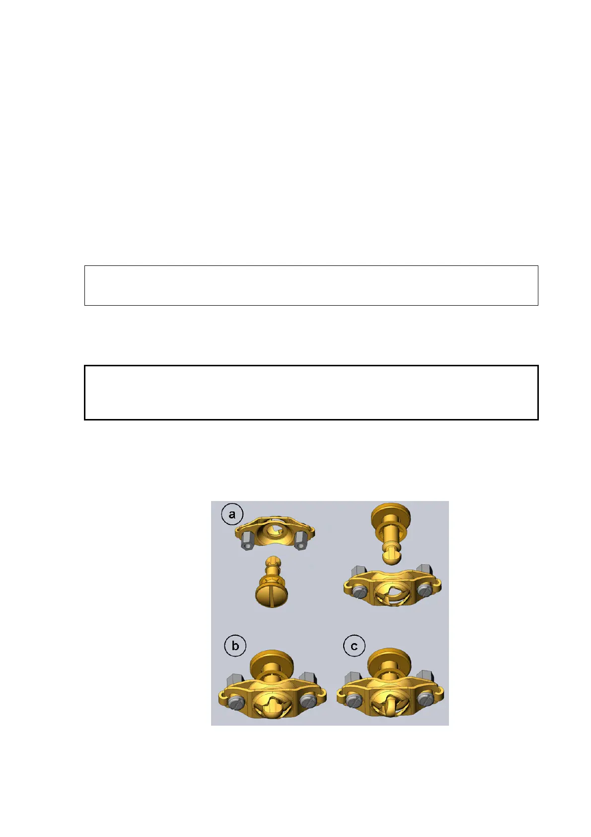
a. Use a screwdriver of suitable size and align the lock screw so
that the screw slot is in an upright position which ensures that
the screw stud fits into the associated receptacle of the
support unit (see Figure 97 a below).
NOTE
The figure shows the basic mechanism only; no ejector spring or sheet
metal items are shown.
b. Insert the lock screw into the associated receptacle while
keeping the screw slot upright (see Figure 97 b below).
CAUTION
Be sure to insert the lock screw into the associated receptacle only with
the correct orientation. Otherwise the receptacle mechanism might be
damaged!
c. When the lock screw is completely inserted and the sheet
metal of the measurement head cover is pressed against the
support unit, the screw is to be fastened by a quarter
clockwise turn (see Figure 97 c below).
0906-096
Figure 97 Using Lock Screws at Measurement Head Cover