User's Guide ______________________________________________________________________
46 __________________________________________________________________ M210667EN-C
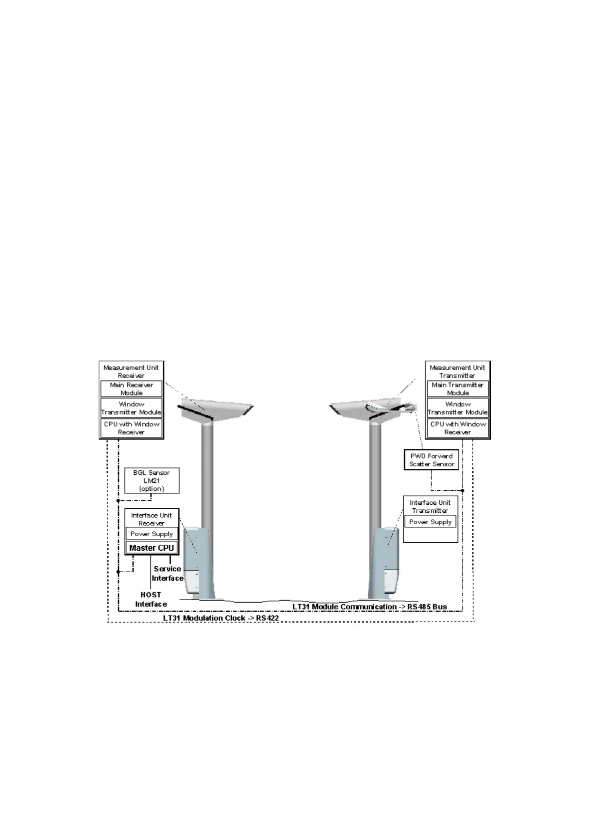
- Transmitter interface unit (power supply and terminals)
- Receiver interface unit (power supply and terminals, master CPU)
- Transmitter measurement unit (measurement CPU, main transmitter
module, and window transmitter module)
- Receiver measurement unit (measurement CPU, main receiver
module, and window transmitter module)
- PWD forward scatter sensor
- Background luminance sensor LM21 (optional)
At least four of the intelligent units of the measurement system (master
CPU, transmitter measurement CPU, receiver measurement CPU, PWD)
are connected by the RS-485, the LT31 internal communication bus
(called the module bus). Furthermore, the modulation clock of the main
transmitter module is transmitted to the receiver measurement unit using
RS-422 technology.
Figure 12 below gives an overview of the location of the functional units
and how they are connected.
0401-029
Figure 12 Communication Principle