User's Guide ______________________________________________________________________
234 _________________________________________________________________ M210667EN-C
value. The expected Maximum Receiver Signal value is a calculated
value which is derived from the configured baseline length. A reading
of a 100 % or even above is not an indication of a Main Receiver
Signal saturation. The absolute value of the displayed Main Receiver
Signal has no direct relation to the prevailing transmittance since it is
a non-calibrated reading.
Furthermore the currently active calibration values Offset and
CALfact are displayed.
The lower part is used for user interaction.
Any action is started by simply pressing the appropriate key:
A Start Offset and Visibility Calibration
B Start Visibility Calibration only
All status information have to be read as OK for proper operation during
the calibration.
During offset calibration, the optical path is blocked and the system uses
the remaining Main Receiver signal as the offset value.
During the menu-guided procedure, the zero signal level (offset) without
any receiver signal (receiver optical system blocked) and the signal level
in accordance to the prevailing visibility are measured. LT31 calculates
automatically the appropriate calibration parameters from these two
measurement values in combination with the information about the
prevailing visibility. The visibility information can be created either from
the integrated PWD Sensor or from an observer estimation. After
finalising the procedure, the calibration parameters are automatically
stored.
Before any visibility calibration, all the optical surfaces of the
transmitter/receiver measurement unit and PWD sensor have to be
cleaned.
NOTE
Always select the offset and visibility calibration mode for the initial
calibration during installation or in the frame of periodic maintenance.
Offset and Visibility Calibration
To start the offset and visibility calibration, press A in the Calibration
menu.
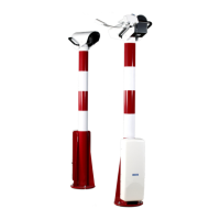
Have the optical blocker available, to block the optical path at the
receiver measurement head. Figure 133 on page 235 shows the optical
blocker mounted.

 Loading...