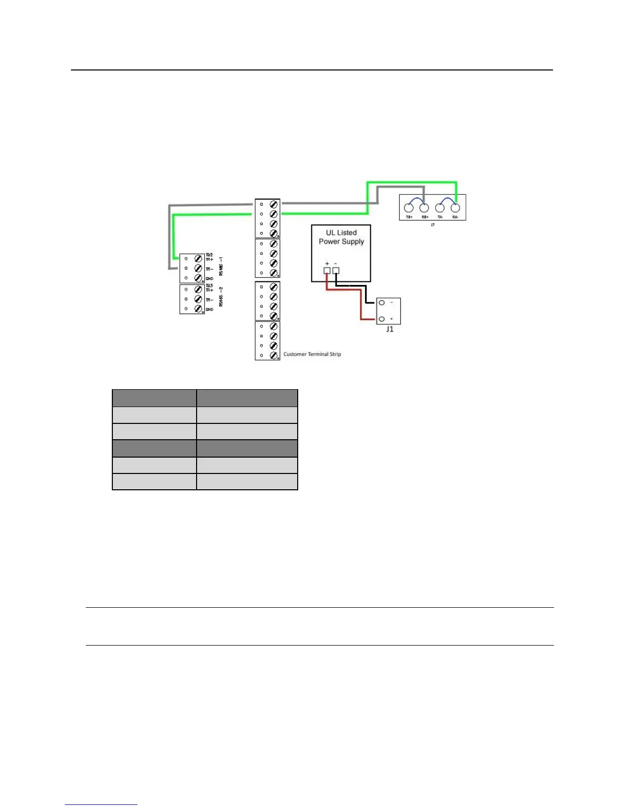
Wiring between lite blue and PIM Module
The PIM receives power at J1 and data at J7. J7 has two pins for Data A and two pins for Data B. The Data A pins
(TA- and RA-) must be jumpered together. The Data B pins (TB+ and RB+) must also be jumpered together. The
below example is using RS485-1 on the lite blue board to J7 and J1 on the PIM.
Data Communication and Power between lite blue and PIM-SBB
Wireless reader modules configuration
The Schlage Wireless Configuration & Demonstration Tool (CDT) must be used to assign each PIM-SBB an
address and to address each WAPM connected to it.
A maximum of eight (8) wireless readers can communicate with a PIM module on the same channel, with all
reader types when used with lite blue. Address can be 0 through 7 (panel number 0 to 7 in the CDT). Example - if
a WAPM is configured as Panel 5 (door 5) using the CDT, then its corresponding address in lite blue is five (5).
Note: All other devices use address 1 through 8. Do not allow the device addresses to overlap when using non-
wireless devices in tandem with wireless devices. Example: wireless devices using addresses 0 through 5 require
any non-wireless devices to start their addressing at 7.