Addressing the VIP Lock
There are a set of 12 dip switches on the VIP lock, the first four of which are used to set the address for the
device. It is recommended that the set address correspond to the order in which the device is connected to the
lite blue controller. For example if the VIP is connected directly to the lite blue controller at RS485-1 then the
switches on the VIP should equal 1. If the VIP is connected to another compatible RS-485 device at the 2
nd
position in a daisy chain, then the dip switches should equal 2. VIP addressing is independent on each RS-485
data channel. Two VIP locks can have an identical VIP address if on different lite blue RS-485 data channels.
After the VIP has been connected to the lite blue controller, make a note of the address. This information will be
required to set up the lock in the software.
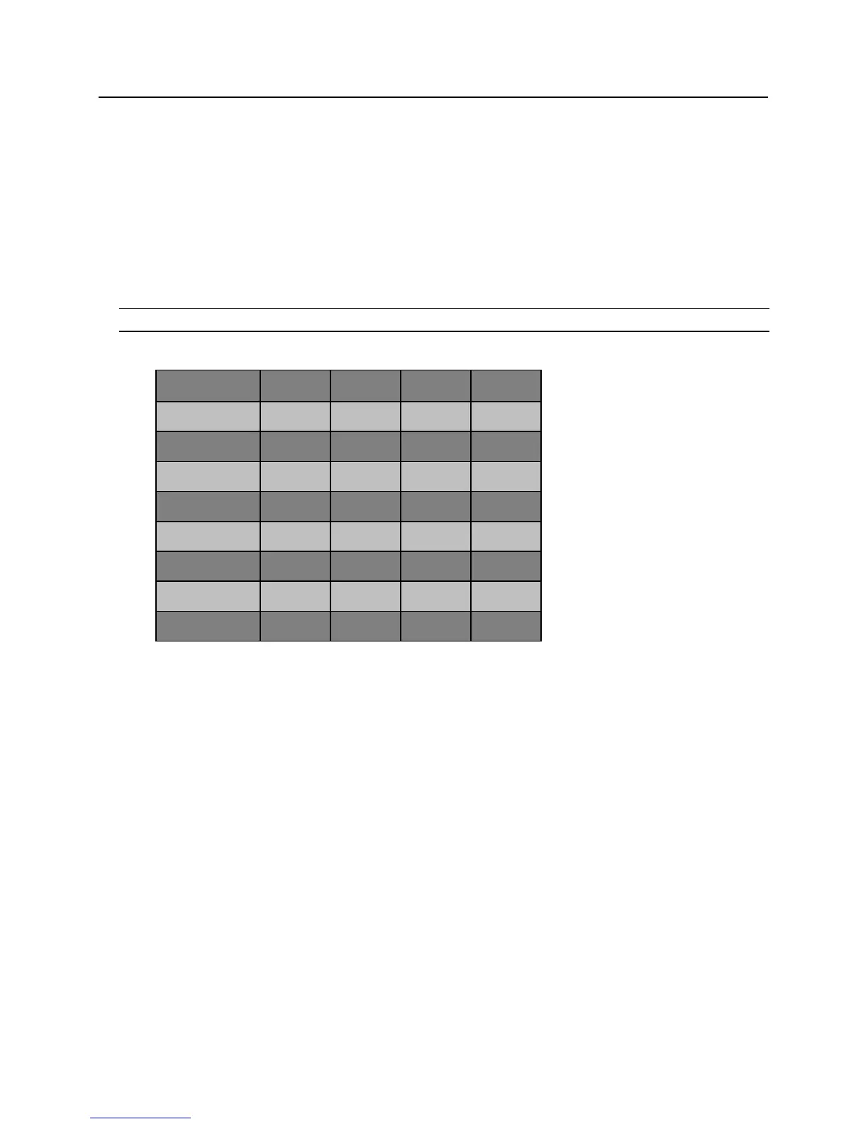
Note: Only the first 4 switches are used for addressing.
VIP Address Chart