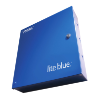
Power method 1 - Single Power Supply
In this method a single UL Listed Power Limited power supply is used:
Connect power cables from the power supply to TB1 GND and VIN in order to power lite blue
Connect additional cables from the same power supply to the peripheral devices as needed
Power method 2 - Multiple Power Supplies
In this method multiple UL Listed Power Limited power supplies are used:
Connect one power supply to TB1 GND and VIN to power lite blue
Connect additional power supplies to power peripheral devices as needed
Configuration Guidelines
The lite blue controller has 2 data channels to connect devices via an RS-485 communication protocol and
2 reader interfaces (Channel 0) supporting Wiegand or Magstripe reader heads. Each RS-485 data channel
port can support up to 8 devices. A total of 8 devices for all channels can be connected to lite blue.
lite blue on board reader interfaces will provide power to the connected reader devices. RS-485 devices
must be powered independently.
lite blue allows different types of RS-485 devices (VBB-RI, AD-300, VIP, AD-400 Wireless) to use the
same data channel.
The data connections for every device on the same channel must be properly connected in a daisy chain
and then back to RS458-1 or RS485-2 TR+ and TR-.
A UL Listed Power Limited, Power Supply capable of 4 hours standby power will be needed to provide
power to the external devices.
Please refer to power requirements for each device connecting to lite blue.
Devices must be powered independently of lite blue with a local power source.
Installation and Configuration Steps
1 Mount lite blue controller to wall.
2 Connect all peripheral devices (VBB-RI, VBB-NRI, Wiegand Readers, AD-300, VIP, PIM or PIM-400). See
specific device chapters for details.
3 Connect 12 VDC or 24VDC power supply to TB1 GND and VIN of the lite blue controller.
4 Connect power to all external devices independently as needed.
5 Turn on the power supply to lite blue and any additional power supplies.
6 Configure the lite blue IP address, date and time. See the lite blue IP Configuration and lite blue Date
and Time setup section for details.

 Loading...