EasyManuals Logo

Vanderbilt lite blue User Manual

Vanderbilt lite blue
152 pages
To Next Page IconTo Next Page
To Previous Page IconTo Previous Page
Page #48 background imageLoading...
Page #48 background image
VLBIM06/15/15 v4.1.0
Chapter 2 VBB-RI 47
W4 - Determines the configuration of the first pin (TXBW0) at P3.
Default: Jumper on pins 5&6
W5 - Determines the configuration of the third pin (RXA) at P4.
Default: Jumper on pins 3&4
W6 - P4 Pin2/Pin3 RS485 Communication Line Terminator.
Default: No Jumper
W7 - Determines the configuration of the second pin (TXB) at P4.
Default: Jumper on pins 1&2
Pins Not Used
W9 - BKDG: No jumper required for normal operation.
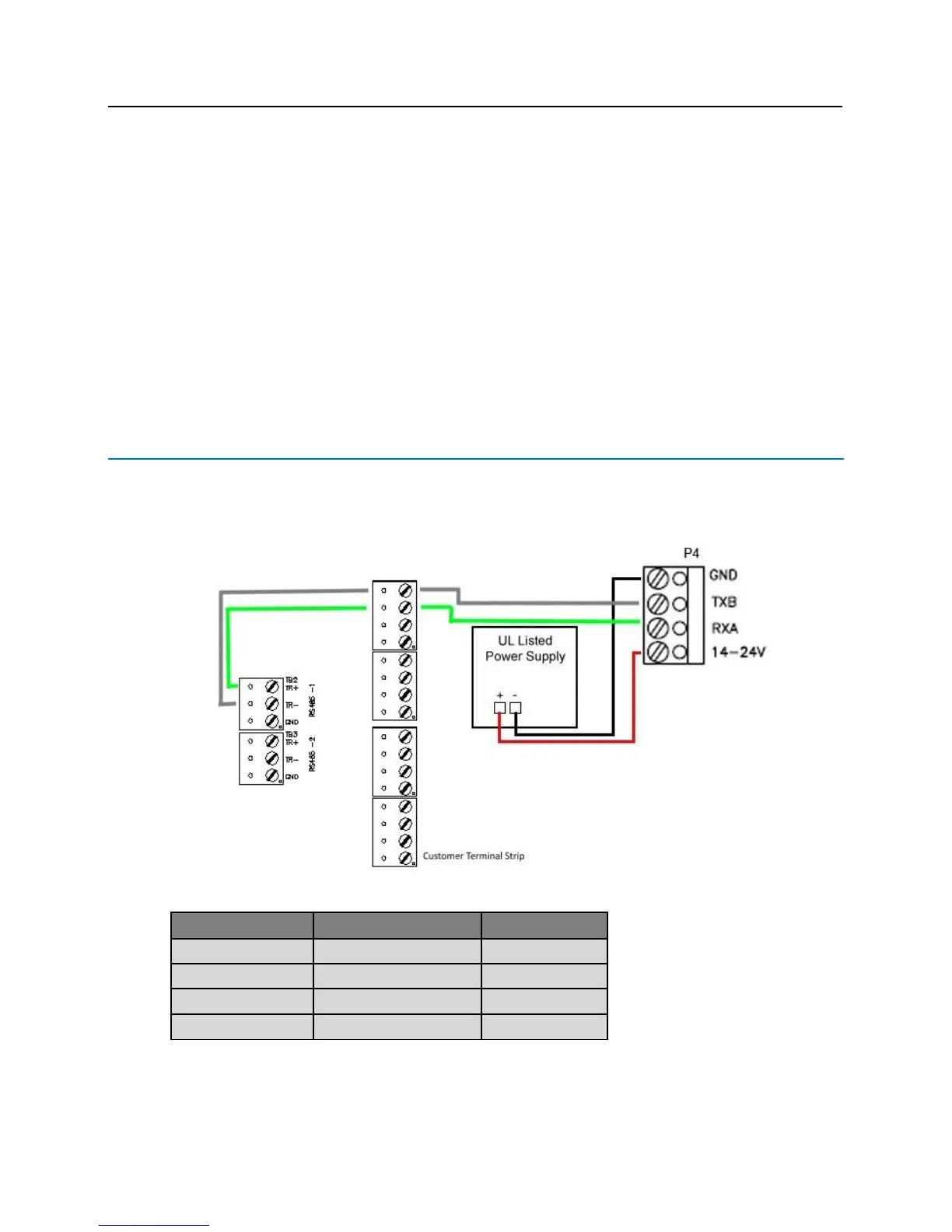
Connecting to lite blue
Data communication between the lite blue controller and a VBB-RI reader interface is via RS-485 protocol. Either
RS-485 channel on the lite blue controller can be used to communicate with P4 on a VBB-RI. The below
example is using RS485-1 on the lite blue controller and P4 on the VBB-RI.
Data Communication between lite blue and VBB-RI
lite blue
VBB-RI
Power Supply
RS-485-1 TR+
Pin 3 - RXA (Data A)
RS-485-1 TR-
Pin 2 - TXB (Data B)
Pin 4 - PWR (Power)
+ (Power)
Pin 1 - GND (Ground)
- (Ground)

Table of Contents

Questions and Answers:

Question and Answer IconNeed help?

Do you have a question about the Vanderbilt lite blue and is the answer not in the manual?

Vanderbilt lite blue Specifications

General IconGeneral
BrandVanderbilt
Modellite blue
CategoryController
LanguageEnglish

Related product manuals