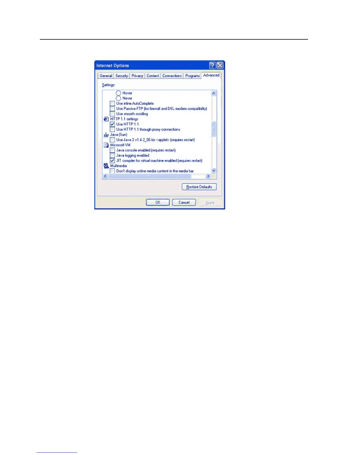
3 Go to the Advanced tab.
4 Uncheck the option Use Java 2x1.4.2-06 for <applet> (requires to start).
5 Click OK.
6 If there are any problems, restart the CDT application.
Configuring PIM
The next step is defining the PIM address by placing the PIM in to Link Mode. Follow these instructions.
1 After the CDT software has been installed, execute WirelessDemo.html from the Wireless Demo folder.
2 For PIM Status, select the proper com port from the drop down menu.
3 Connect the PIM to the PC using a DB9 female to DB9 male that is connected to the PIM RS232 port.
4 After this connection is made, hold down one of the PIM link switches (SA or SB).
a) Continue to hold the link switch and press the reset button (S3). Do not stop pressing the link switch.
b) The LED’s (CR6 – 10) on the PIM begin flashing, displaying the firmware version of the PIM. When
completed, (CR7 and 10) will continue to flash RED and CR15 will be continue to blink GREEN. At this
point, the PIM will be in the CDT link mode as long as the CDT program on the PC remains running and
connected to the PIM.
c) Release the link switch.
d) On the CDT screen, under PIM Status you should now see the "PIM Connected on Proper Com Port"
message.
5 Using the Addresses tab, set the address of the PIM.
a) If one PIM is being used per channel set the PIM Addr to 0.