EasyManua.ls Logo

Vanderbilt lite blue - Page 25

Vanderbilt lite blue
152 pages
Print Icon
To Next Page IconTo Next Page
To Previous Page IconTo Previous Page
Loading...
24 lite blue Installation Manual
S2 - RESET -- DO NOT USE.
JP3 [CPU Daughter Board] - DO NOT REMOVE.
J4 [CPU Daughter Board] - RS-232
S1 [CPU Daughter Board] - RESET -- DO NOT USE.
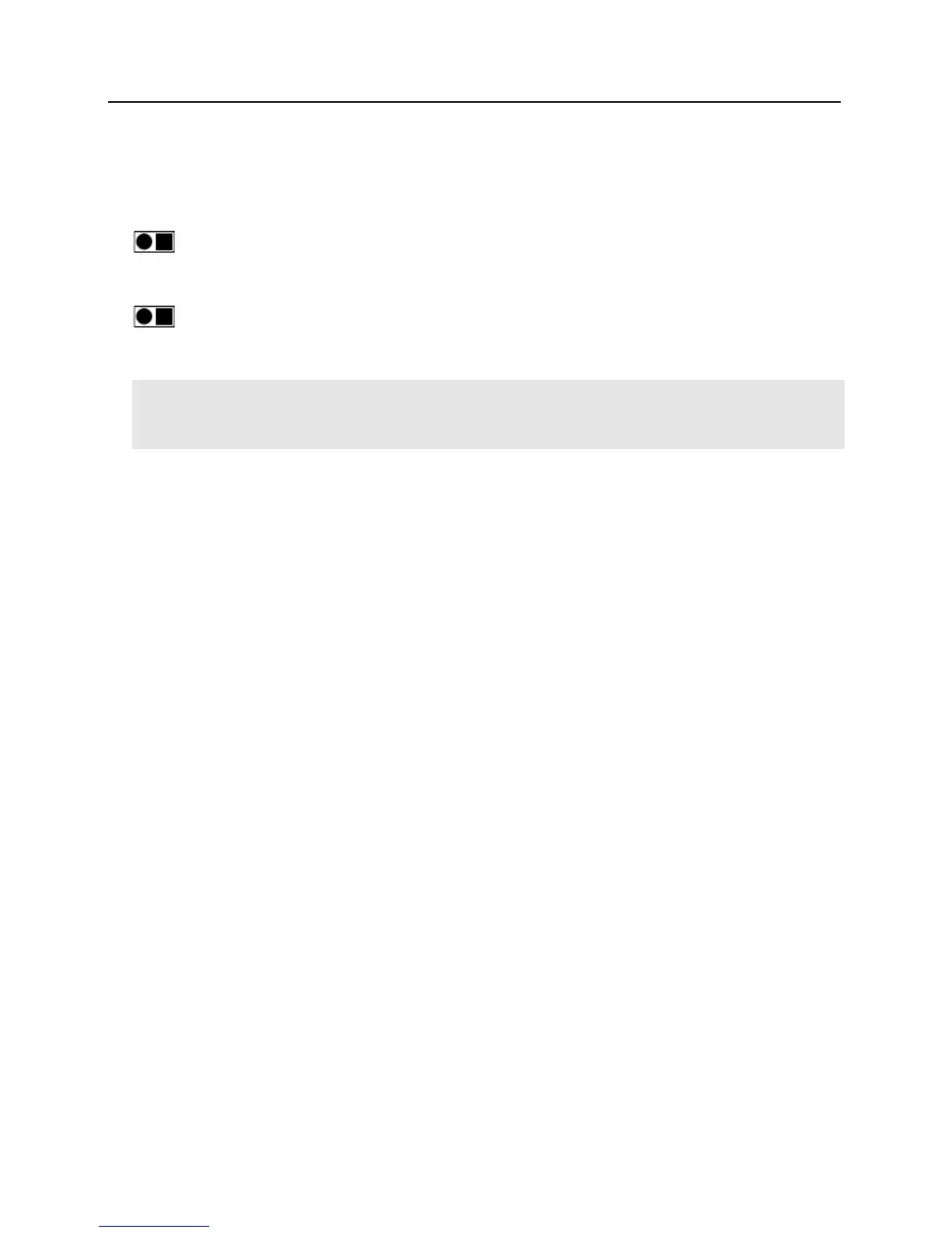
Never Depress the S2 RESET button on the main controller or S1 RESET button on the CPU daughter board.
These buttons will interrupt power to the VLB without shutting down critical software processes and may render
the lite blue system inoperable.
READER 1 - Onboard Reader Interface (Wiegand / Magstripe)
GND
Ground
DAT
D0
Data / Data 0
CLK
D1
Clock / Data 1
BZR
Reader Buzzer
LED
Reader LED
VO
Reader Power
READER 2 - Onboard Reader Interface (Wiegand / Magstripe)
GND
Ground
DAT
D0
Data / Data 0
CLK
D1
Clock / Data 1
BZR
Reader Buzzer
LED
Reader LED
VO
Reader Power
OUT 1 - Relay Output 1 for Reader 1
NO
Normally Open
C
Common
NC
Normally Closed

Table of Contents

Related product manuals