Pin 4 is Ground
Pin 3 is Data B
Pin 2 is Data A
Pin 1 is Power
P1 - Contact Inputs. The SBB-RI has four unsupervised contact points. When connecting more than two contact
inputs to Pin 8 (GND), a terminal strip to connect the common ground wires needs to be installed. Unsupervised
door contacts have maximum wire length of 2,000 feet.
Pin 1 is Exit Request (REX) - Normally Open
Pin 2 is Door Position Switch (DOD) - Normally Closed
Pin 3 is Push Button Override - Normally Open
Pin 4 is Auxiliary Input - Normally Closed
Pin 5 is Not Used
Pin 5 is Not Used
Pin 6 is Not Used
Pin 7 is Not Used
Pin 8 is Ground
P5/P6 - Relay outputs. The SBB-RI comes with two relay output. The relays are single pole/double throw and are
rated at 30 VDC @ 2 amp.
Pin 1 - Normally Open
Pin 2 - Normally Closed
Pin 3 - Common
W5 - Factory use only. Do not add a jumper under normal operating conditions.
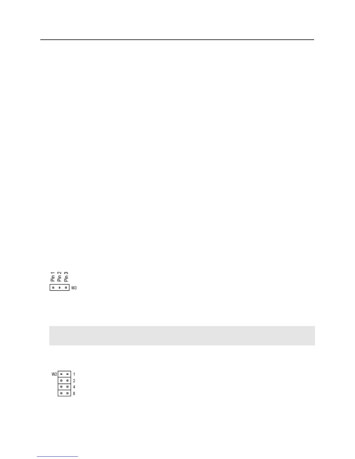
W3 - Read head voltage selector. The SBB-RI read-head voltage selector provides 5VDC or 12VDC to the
various types of read-heads depending on jumper location.
No jumper will provide 5VDC
A jumper across Pins 1 and 2 will also provide 5VDC
A jumper across Pins 2 and 3 will provide 12VDC
Warning: Serious damage may occur to the read-head if this jumper is set incorrectly. Please check the read-
head voltage requirements.
W2 - SBB-RI addressing. The address of the SBB-RI is dependent on the position of jumpers on these pins.
Please see the section on Addressing SBB-RI for more details.