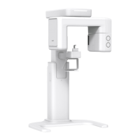
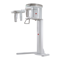
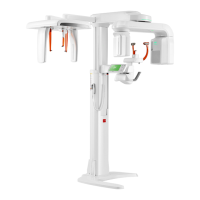
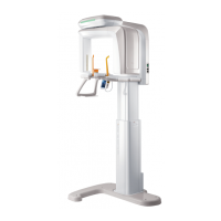
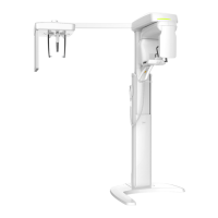
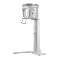
Smart Plus (PHT-35LHS)
Technical Manual
VT-TECH-Smart Plus-001
COPYRIGHT© 2018 VATECH.
① Close the Viewer.
② In the Panorama tab, type [SPM_PO?_] and click Send to read the current POFS value.
③ Correct the POFS value and type [SPM_POFS_####] and click Send.
####: Corrected POFS value
(0#### = + ####, 1#### = - ####)
When you change POFS Value 50, it will be changed by approximately 4 pixels.
- Increase POFS Value Increase Pixel Number of Center Pin
- Decrease POFS Value Decrease Pixel Number of Center Pin
- The above Pixel shift value is not an absolute measure.
If the Pixel Number of Center Pin meets the standard, but the ghost image doesn’t
have bilateral symmetry, change PLST Value to adjust the ghost image symmetry.
[SPM_PL? _]: Query the current PANO sensor tilting offset position
[SPM_PLST_####]: Set PANO sensor tilting offset position by ####.
5) 4Exit VAKCAP and acquire the BALL PHANTOM image again.
6) Make sure that the center pin position meets the standard and that the ghost image has
bilateral symmetry.
7) Do the steps repeatedly until the center pin position calibration is completed.
For the Center Pin Calibration, ① Pixel Number of Center Pin must meet the standard
and ② the ghost image must have bilateral symmetry.