48 Vectorworks 2010 Products
Vectorworks Spotlight 2010 Getting Started Guide
Wall Tool
Select the Building Shell Tool Set and select the Wall tool. Select the right control line option in the Tool Bar and set the wall’s Overall
Thickness at 9” [228.6mm] in the Wall Tool Preferences in the Tool Bar. Click on the locus, drag up, tab into the Floating Data Bar and
enter 30’ [9.144m] in the length; tab to the wall angle and set to 90°. Hit return and click on your page. Drag to the right. Tab into the
FDB and enter 70’ [21.336m] at 0°, hit return, and click and drag down the page. Tab into the FDB and enter 30’ [9.144m] with -90°,
click return and double click.
With the Wall tool still selected, go back to the wall preferences and change the wall thickness to 24” [.610m]. Select left control line
option. Click on the Off stage edge of the DSR (Down Stage Right) wall and drag to the off stage edge of the DSL (Down Stage Left)
wall. Double click. Use the Zoom Loupe as needed.
It is likely that the three walls we rst drew will be separate from the new wall; select the Wall Join tool, click on SR wall and drag to the
thick wall. Repeat on the SL side.
Select all the walls and change the wall height (+Z) to 50’ [15.240m] in the OIP.
Floors
Select the Rectangle tool from the Basic Tool Set. Click on the
USR outside corner of the wall structure and drag to the outside
corner point of the DSL. Your theatre has disappeared! We’ll get it
right back.
Go to AEC>Floor and set the bottom Z to -36” -[.914m] and the
thickness to 36” [.914m] and click OK. Go to Modify>Send>Send
to Back. Bam! The theatre has returned and you have a stage.
Note: Extruding objects with a positive value extrudes them up
from the zero Z and extruding with a negative value extrudes down
from zero.
Door and Window Tools
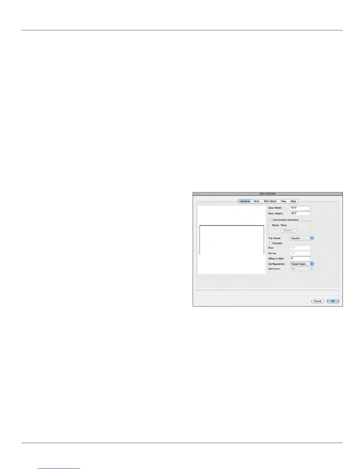
Now we need a proscenium opening. From the Building Shell Tool Set, select the Door Tool and hover over the middle of the down
stage wall. The Smart Cursor will indicate “Midpoint” when you are in the right place. Double click to insert the door. Don’t worry about
the size or the swing direction. When the Door Settings dialog opens, select the General tab and set the opening to 40’ [12.192m]
wide and 18’ [5.4864m] tall and change the conguration to Cased Opening. Click OK. At any time, use the Flyover tool, the numeric
keypad or the Current View drop down in the View Bar to admire your work.
Note: The Window tool work in the same basic manner as the Door tool.
Now we need some basic masking.