Vectorworks 2010 Products 67
Vectorworks Spotlight 2010 Getting Started Guide
Creating Custom Lighting Symbols
Any hybrid symbol can be made into a Lighting Symbol by selecting the symbol in the document and going to Modify>Convert>
Convert to Instrument. In this way, you can place a symbol to represent a practical and be accounted for in your paperwork.
You want that thing to light up?
Not a problem, but we’re going to discuss Vectorworks lights in the next section. Once you review that section, you can come back,
edit your 3D symbol and insert a light. If you are looking to represent a specic lamp type, Vectorworks has a great le of lamps in the
library. You can also import IES data from manufacturers specs to make a specic effect.
Be sure that your symbol either uses the default instrument texture or a texture with cast shadows unchecked for the light to pass out of
the instrument.
Create Plot and Model View
OK, now let’s stand up those booms and get this thing ready for presentation. We have a model and we have lights, but we don’t have
a plot that tells the electricians what to do with that pile of gear.
The Create Plot and Model View command will create a Denition Layer for the boom(s) selected. From that Denition Layer it places
a Design Layer Viewport (DLVP) of the boom(s) in plan on the Plot Layer (this is your 2D Light Plot View). It will also place a DLVP of
the Denition Layer on a new or existing Model Layer. The Model Layer (after you have rotated the booms is used for stage sections
and (rendering).
First a few critical issues:
You must have a layer structure as I have previously described.
•
Your lights and positions must be on one layer.•
If your focus objects are on the layer with your lights and positions, they should be classed together and invisible.•
Be sure that you do not have any Sheet Layer Viewports created that reference the Plot Layer•
Select one of the vertical positions and associated units. Go to View>Create Plot and Model View.
The Create Plot and Model View command moves the selected lights and lighting
positions to a new design layer and references them back to your Plot Layer as
a Design Layer View Port (DLVP). Create Plot and Model also places a DLVP on
an existing Model Layer or it will create a new Model Layer.
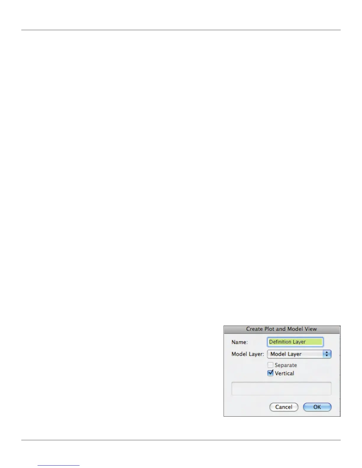
The rst dialogue in the process names the new Denition Layer. Since we have
two vertical positions, we will run this command twice. Name each Denition
Layer so you can identify your positions. Check the box next to Vertical.