External Control
TVM Series Installation and Operation Handbook 207
Copyright © 2008, Harris Corporation
• Initiate, display, and transfer frame captures from the TVM/VTM
SpyderWeb II uses a network connection for monitoring and control of up to 30
TVM/TVM series units. The SpyderWeb II program runs cooperatively with other
Windows
®
programs. It runs “in the background” of a PC using a Windows operating
system, allowing use of the PC for other tasks. SpyderWeb II alarms the user of any
problems detected in any of the connected TVMs/TVMs.
Browser Interface
The website for each unit is accessed by pointing the web browser at the TVM/TVM IP
address. Before the default web screen appears, a password must be entered to access
the instrument. Each password allows specific privileges. The following passwords are
case-sensitive:
• VTMUser: Allows read-only access to the instrument
• VTMSystem: Allows read/write access to instrument
• VTMAdmin: Allows read/write access to instrument.
Once the password has been entered, the default web page (the ABOUT Screen), is the
first screen that appears. The screen indicates the model number, version, serial
number, and what is installed in each slot of the instrument.
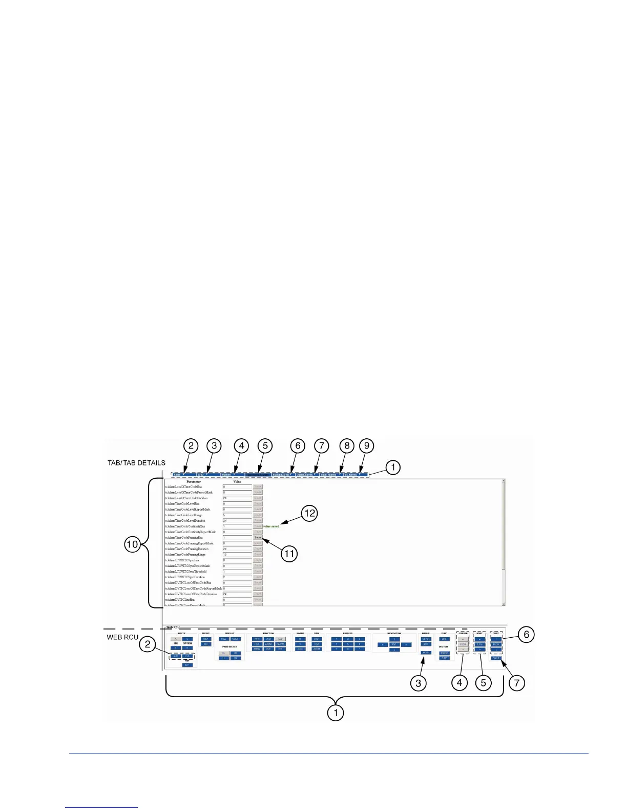
A sample Web Remote Display is shown in Figure 6-1, and described in Table 6-3.
The screen is split into two sections. The sections are the Tab/Tab details section and
the Web RCU section.
Figure 6-1. Sample Web Remote Display