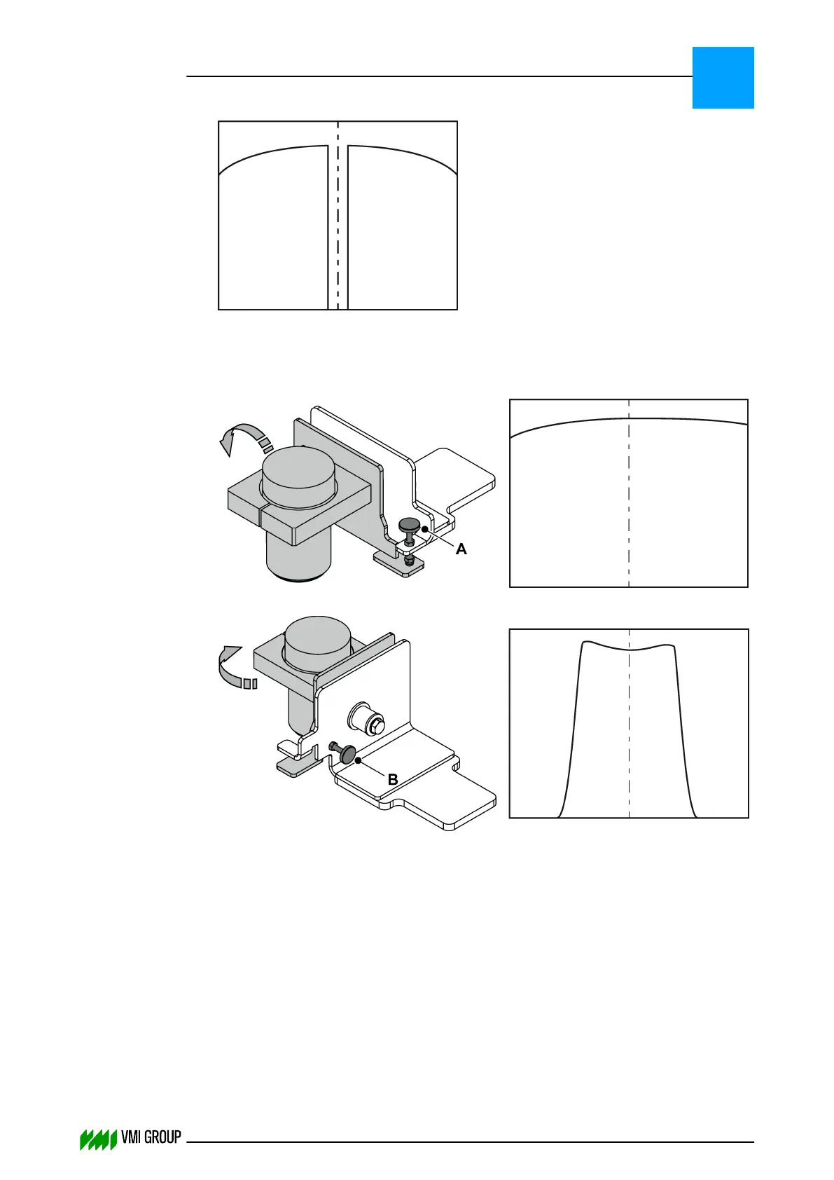
6. If necessary, use the adjustment screws [A], [B, [C] to adjust the camera image.
The following illustrations show a simplified display view when the camera is not
aligned.
Adjustment screw [A]:
Adjustment screw [B]:
Adjustment screw [C]:
ALIGNMENTS, ADJUSTMENTS AND CALIBRATIONS
VVS Tread
5
THINKING FORWARD
VMI Vision System VVS (OL82) VVSX 13.0.12.0, VVSU 3.0.6 / 4 / 2016-07-11 / pd#175592
5-27