8.
Turn the focus ring [3] until the narrow spikes almost have the same intensity as the
baseline in the DISPLAY SENSOR screen.
NOTICE
When the gray lens filter (B&W type 103) is mounted on the lens cover, you must
place or hold the cover on lens to check the camera image.
9. Remove the calibration template.
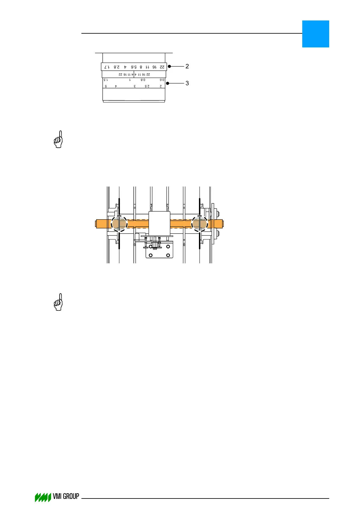
10. Place a cable tie on each side of the conveyor belt as follows:
In the DISPLAY SENSOR tab, the cable ties are visible as spikes.
11. Position the left and right rulers of the camera image just outside of the spikes.
NOTICE
Make sure that you move the rulers always a bit before you click SAVE EDGES.
Otherwise, it is possible that the edge positions are not sent to the camera.
12. Click SAVE EDGES to send the new Region Of Interest to the camera.
13. Remove the cable ties.
14. Mount the lens protection cover [1].
15. Enable the white balance:
● In VVSU, go to tab SENSOR.
● Change the value of Start Service to 10 and pres ENTER.
● Click TRANSMIT to send the values to VVSX.
After a few seconds the value returns to 0.
16. Check if the intensity of the camera image is between 150 - 230.
Use the mouse pointer in DISPLAY SENSOR to determine the intensity.
17. Fix the adjustment screws [A], [B, [C] settings with the lock nuts.
ALIGNMENTS, ADJUSTMENTS AND CALIBRATIONS
VVS Tread
5
THINKING FORWARD
VMI Vision System VVS (OL82) VVSX 13.0.12.0, VVSU 3.0.6 / 4 / 2016-07-11 / pd#175592
5-29