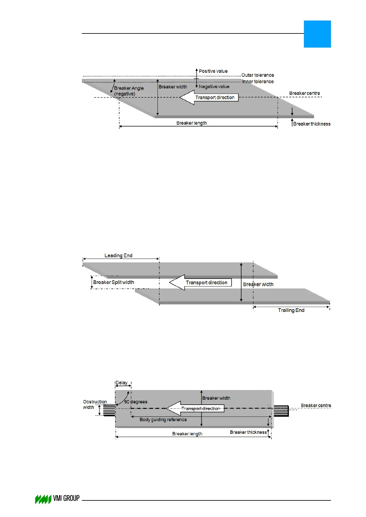
6.2.1.3 Breaker dimensions
The Breaker angle is measured in respect to the side of the breaker. A negative angle
means the leading end is on the right‑hand side (see illustration). A positive angle means
the leading end is on the left‑hand side (mirror image of the illustration).
Breaker width + Outer tolerance = maximum allowed breaker width.
Breaker width – Inner tolerance = minimum allowed breaker width.
The measured breaker width is the running average over 150 samples.
The Breaker length is measured at the center line of the breaker.
The Calibration length is set by the PLC during calibration of the encoder for length
measurement. For more information, refer to the paragraph Encoder calibration on
page 5
‑
23.
6.2.1.4 Split breaker
The Breaker split width parameter specifies the distance between both breaker
components.
The Breaker width is the total width of the two components plus the split width.
Due to the split, edge centering is only possible during the leading ends and trailing ends.
6.2.1.5 90° Breaker
The 90° breaker is centered by Body guiding reference (center line between the two
edges) after a delay.
Detected material smaller than the Obstruction width is ignored, to avoid that breaker
centering is started by the support beam instead of the breaker material.
PARAMETERS
Parameter buffer
6
THINKING FORWARD
VMI Vision System VVS (OL82) VVSX 13.0.12.0, VVSU 3.0.6 / 4 / 2016-07-11 / pd#175592
6-6