The actual material edges (as seen by the camera) are represented by a continuous black
line.
The desired material position (as calculated by VVS) is indicated by a red dotted line.
The blue line in the center represents the difference between actual material position and
the desired position (enlarged).
6.2.1.8 Splice correction
The Splice correction parameters are used to correct the splice.
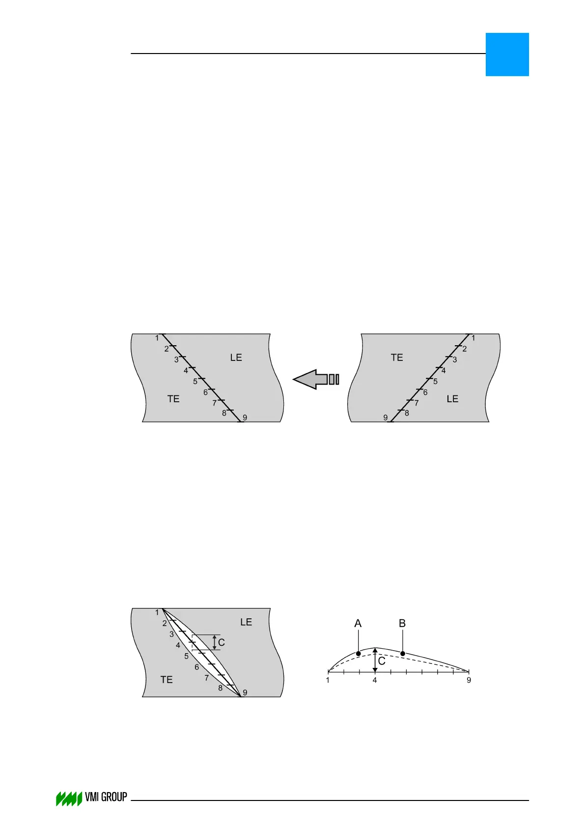
A How to correct the breaker splice
You can influence the quality of the breaker splice. To open or close the splice,
you can correct the splice on nine points.
The splice correction parameters are numbered as follows:
● 1 at the leading‑end tip
● 9 at the end of the splice
The correction is independent from the breaker angle.
The correction of each point is opposite to the transport direction. The correction value of
each point is faded‑in and faded‑out in a linear manner from the start until the end of
the splice. One half of the value effects the leading end, the other half effects
the trailing end.
How to correct the breaker splice
The only way to find the correct values for splice correction is trial and error. When a splice
is open, the starting point for a correction is the point where the opening is the largest.
1. Make sure that all values (that is, all the parameters that specifically relate to
splice correction) are set to zero.
2. Apply a breaker on the B&T drum.
3. Check the splice.
A Total splice
B First correction
4. Measure the opening, at an angle of 90 degrees to the transport direction.
PARAMETERS
Parameter buffer
6
THINKING FORWARD
VMI Vision System VVS (OL82) VVSX 13.0.12.0, VVSU 3.0.6 / 4 / 2016-07-11 / pd#175592
6-9