126 www.xilinx.com Virtex-5 RocketIO GTP Transceiver User Guide
UG196 (v1.3) May 25, 2007
Chapter 7: GTP Receiver (RX)
R
Table 7-2 describes the attributes and settings regarding termination for both receivers of
the GTP_DUAL tile.
Description
The GTP_DUAL receivers are connected via differential pad pairs RXN and RXP to the
transmission line on the board. Figure 7-2 illustrates the internal architecture of one
receiver channel inside the GTP_DUAL block.
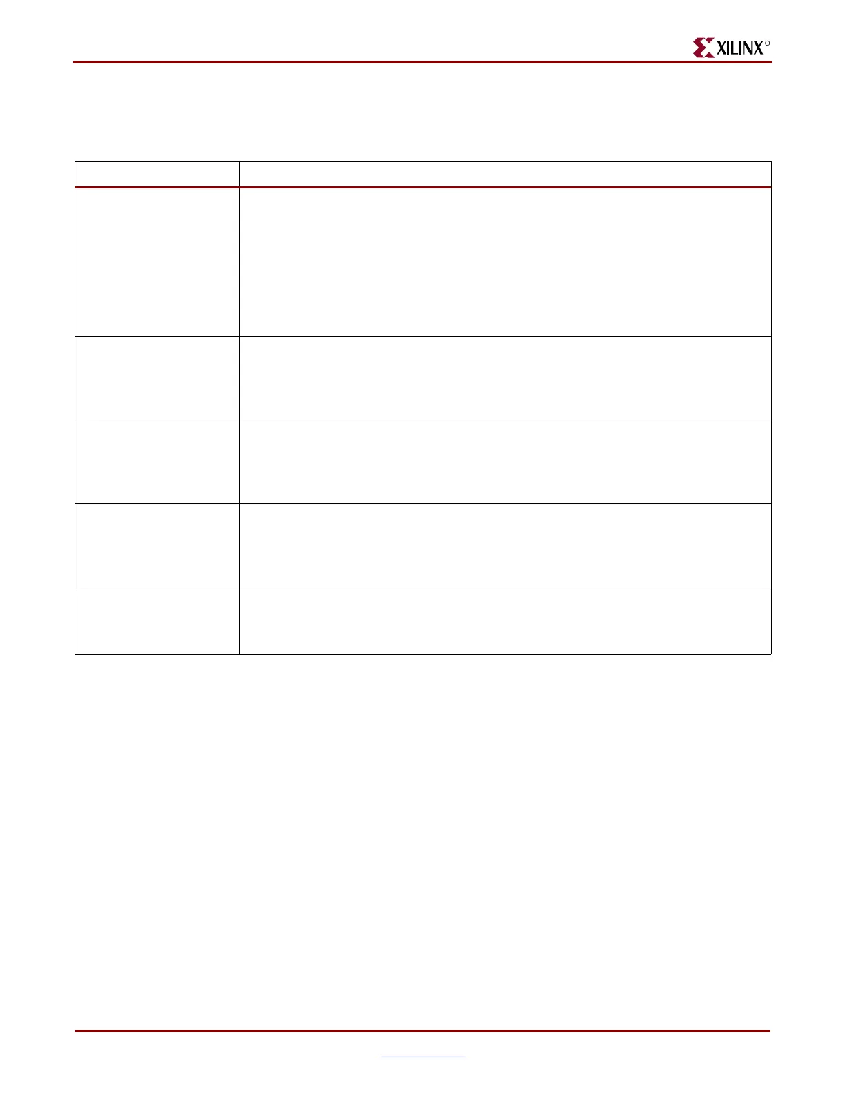
Table 7-2: RX Termination and Equalization Attributes
Attribute Description
AC_CAP_DIS_0
AC_CAP_DIS_1
Bypasses the built-in AC coupling in the receiver. Use this attribute when DC coupling is
required.
TRUE: Built-in AC coupling capacitors are bypassed. DC coupling to the receiver is
possible.
FALSE: Built-in AC coupling capacitors are enabled. This is the default setting for this
parameter.
See Chapter 10, “GTP-to-Board Interface,” for details about when it is appropriate to add
an additional external capacitor for AC coupling.
RCV_TERM_GND_0
RCV_TERM_GND_1
Activates the Ground reference for the receiver termination network.
TRUE: Ground reference for receiver termination activated.
FALSE: Ground reference for receiver termination disabled.
See Table 7-3, page 128 for valid combinations of RX termination attributes.
RCV_TERM_MID_0
RCV_TERM_MID_1
Activates the 2/3 AVTTRX reference for the termination circuit after the built-in AC
coupling circuit in the receiver. RCV_TERM_MID should always be set to !AC_CAP_DIS.
TRUE: 2/3 AVTTRX reference after built-in AC coupling is activated.
FALSE: 2/3 AVTTRX reference after built-in AC coupling is disabled.
RCV_TERM_VTTRX_0
RCV_TERM_VTTRX_1
Activates AVTTRX reference for receiver termination network.
TRUE: AVTTRX reference for receiver termination activated.
FALSE: AVTTRX reference for receiver termination disabled.
See Table 7-3, page 128 for valid combinations of RX termination attributes.
TERMINATION_IMP_0
TERMINATION_IMP_1
Selects the termination impedance for the TX driver and RX CML receiver.
See Chapter 10, “GTP-to-Board Interface,” for details on calibration of impedance values.
Always set to 50, to select 50Ω termination impedance.
 Loading...

