216 www.xilinx.com Virtex-5 RocketIO GTP Transceiver User Guide
UG196 (v1.3) May 25, 2007
Chapter 10: GTP-to-Board Interface
R
SelectIO-to-GTP Crosstalk Guidelines
Because it is possible for GTP transceiver performance can degrade in an environment
flooded with SelectIO™ activity, it is important to have guidelines for SelectIO usage that
minimize the impact on GTP transceiver performance.
Although the Virtex-5 package exhibits little package-related crosstalk issues, the pinout of
the device might lead to customer designs becoming susceptible to PCB-via related
crosstalk issues. The near proximity of SelectIO signals (aggressor) to GTP transceiver
analog supplies (victim) results in their PCB via structures being placed in close proximity
as well. This ball adjacency and resulting via adjacency creates a via-coupling region
between the SelectIO signals and the GTP transceiver analog supplies that is not filtered by
on-board power supply filtering. The amount of crosstalk voltage induced on the victim
circuit by the aggressor circuit is equal to the rate of change of current in the aggressor
times the mutual inductance shared between the two circuits. For an in-depth discussion
on via crosstalk and calculations of mutual inductance for various via configurations, refer
to High-Speed Signal Propagation: Advanced Black Magic by Howard Johnson and Martin
Graham [Ref 5]. The sensitivity of the GTP transceiver analog supplies to coupled noise
from the PCB results in a degradation of GTP transceiver performance. The MGTAVCC
and MGTAVCCPLL supplies are most sensitive to coupled noise.
To minimize the impact on GTP transceiver performance, the following list of BGA
adjacency guidelines must be followed:
•
Avoid utilizing SelectIO nets 1.0 mm (horizontal or vertical) or 1.4 mm (diagonal)
away from GTP transceiver analog power supply pins. Ground these SelectIO
locations in the PCB, and set the SelectIO output to the highest drive and a forced-Low
setting. If these SelectIO outputs must be used, use them either in differential signaling
applications or for static control/status signals with low speed and low drive.
• Avoid using a large number of SelectIO signals in I/O banks near GTP transceivers.
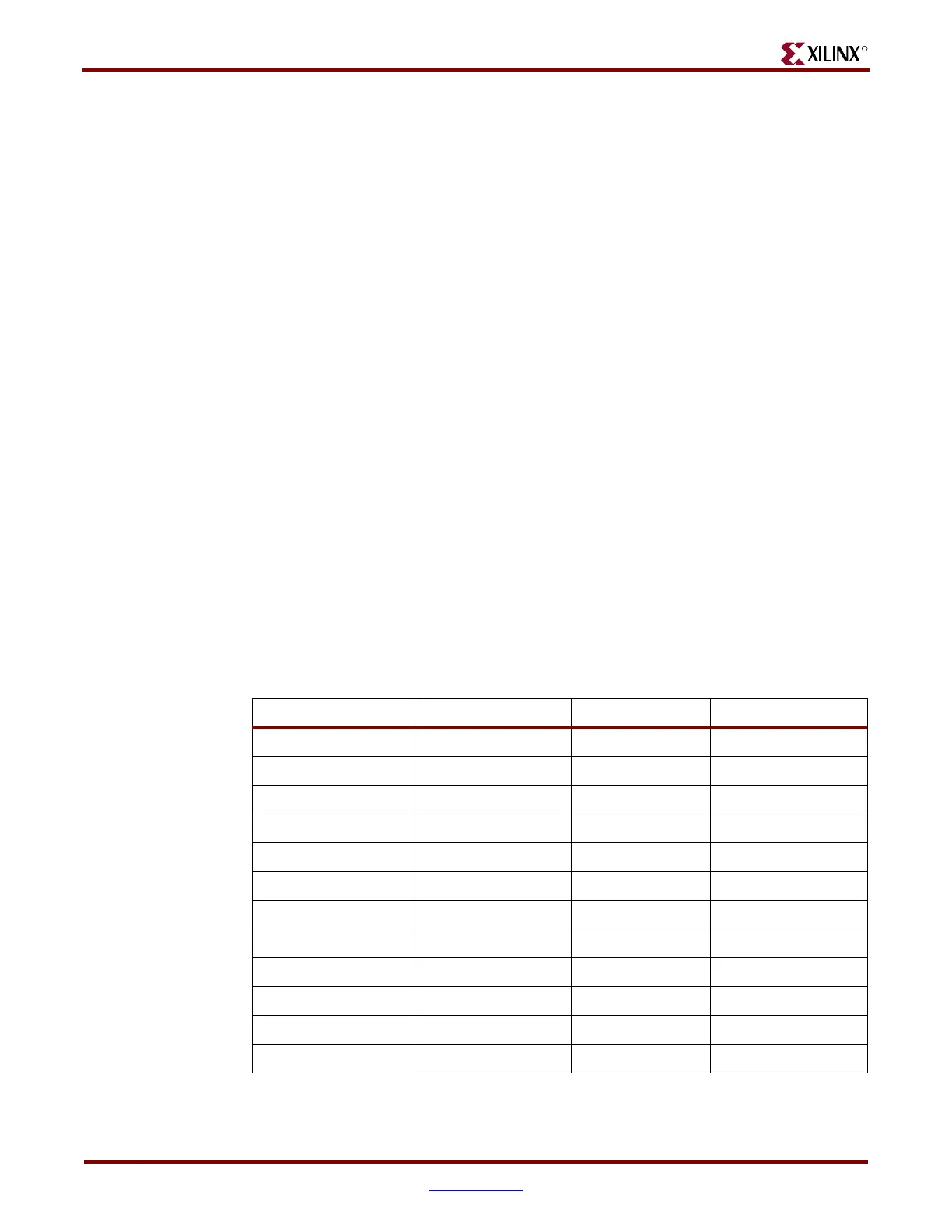
See Table 10-5 for specific aggressive I/O bank to GTP transceiver pairing.
Table 10-5: Aggressive I/O Banks
GTP_DUAL FF665 FF1136 FF1738
MGT112 12 12 12
MGT114 12 18 18
MGT116 12,16 12 12
MGT118 12,18 18 18
MGT120 12 12/20
MGT122 18 26
MGT124 12,20 12/20
MGT126 22 26
MGT128 20
MGT130 34
MGT132 24/5
MGT134 34
 Loading...

