214 www.xilinx.com Virtex-5 RocketIO GTP Transceiver User Guide
UG196 (v1.3) May 25, 2007
Chapter 10: GTP-to-Board Interface
R
Regulator Design Guidelines
The selection criteria for the regulator design are:
• Do not operate the regulator with a V
IN
that is just slightly over V
OUT
+ V
DROPOUT
.
• Keep in mind that the dropout voltage is highly load dependent.
• Remember that the regulator stability and performance are only guaranteed. When
using the correct decoupling capacitors (value, ESR, dielectric material) on input,
output, and bypass pins of the regulator.
• Strictly follow the layout rules of the regulator data sheet.
• Do not max out the output current of the regulator (allow enough headroom under all
operating conditions, especially when it comes to high temperature).
• Place, if possible, the regulator close to the filter network.
• Place the filter network as close as possible to the analog supply pin that it sources.
• Remember that the PSRR of the regulator is output load current and frequency
dependent.
Ferrite Selection Guidelines
The selection criteria for the ferrite are:
• Choose a ferrite with a low DC resistance.
• Do not max out the ferrite current rating
(1)
.
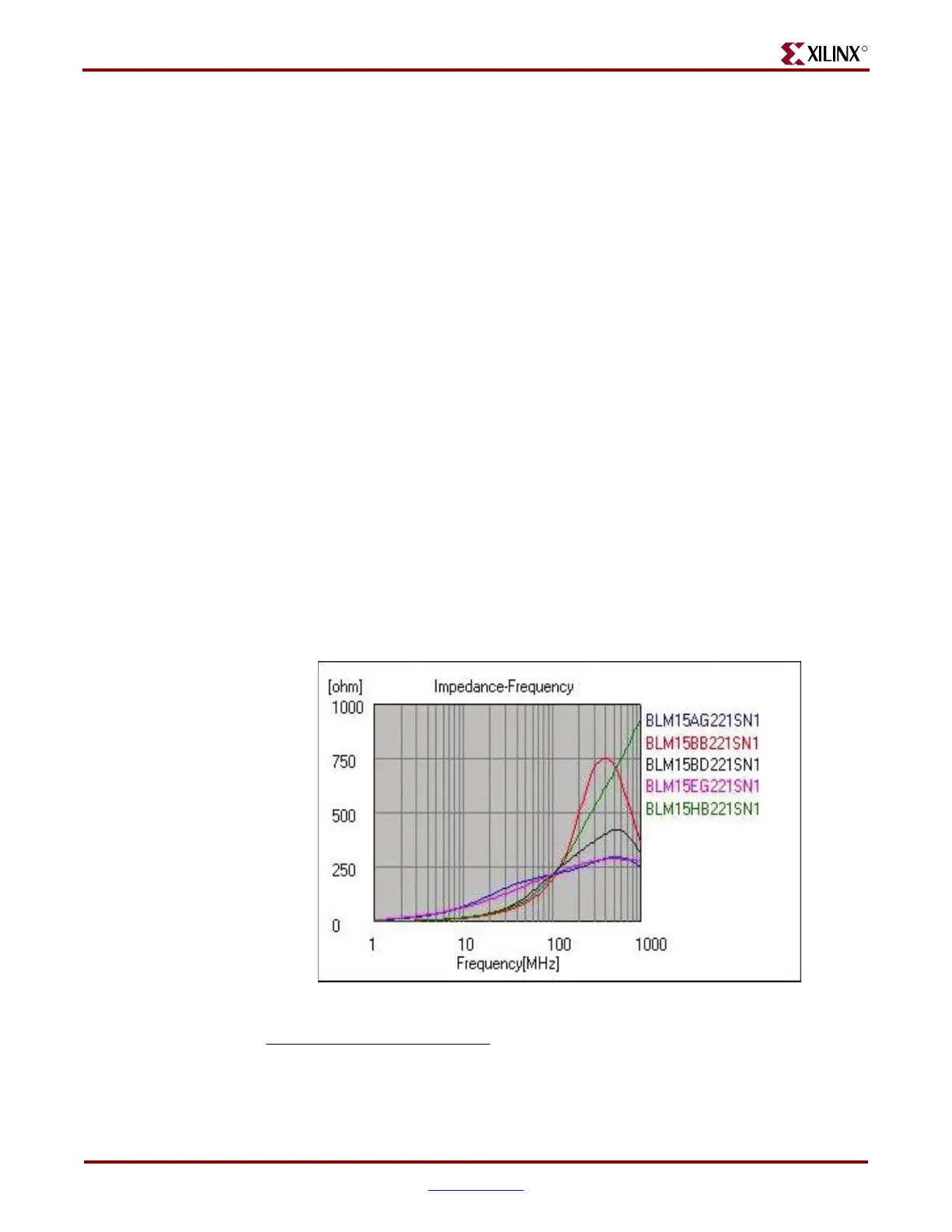
• Choose a ferrite with a high impedance in a frequency range where you expect or
measure the highest spurs or noise levels.
Figure 10-11 illustrates the impedance over frequency characteristics of different ferrites.
1. If the current rating of a ferrite is maxed out, the magnetic material of the ferrite body is in saturation, which
impacts its ability to suppress high frequencies.
Figure 10-11: Impedance over Frequency Characteristics of Different Ferrites
UG196_c10_11_100506
 Loading...

