Virtex-5 RocketIO GTP Transceiver User Guide www.xilinx.com 85
UG196 (v1.3) May 25, 2007
Power Control
R
Powerdown Transition Times
The delays between changes in the powerdown state when TXPOWERDOWN and
RXPOWERDOWN are changed are controlled by the TRANS_TIME_FROM_P2,
TRANS_TIME_NON_P2, and TRANS_TIME_TO_P2 attributes as described in Table 5-10.
Each TRANS_TIME delay is set in terms of internal 25 MHz clock cycles. The internal
25 MHz clock rate is set using the CLK25_DIVIDER attribute and the reference clock rate.
Equation 5-6 is used to determine the actual rate.
Equation 5-6
Examples
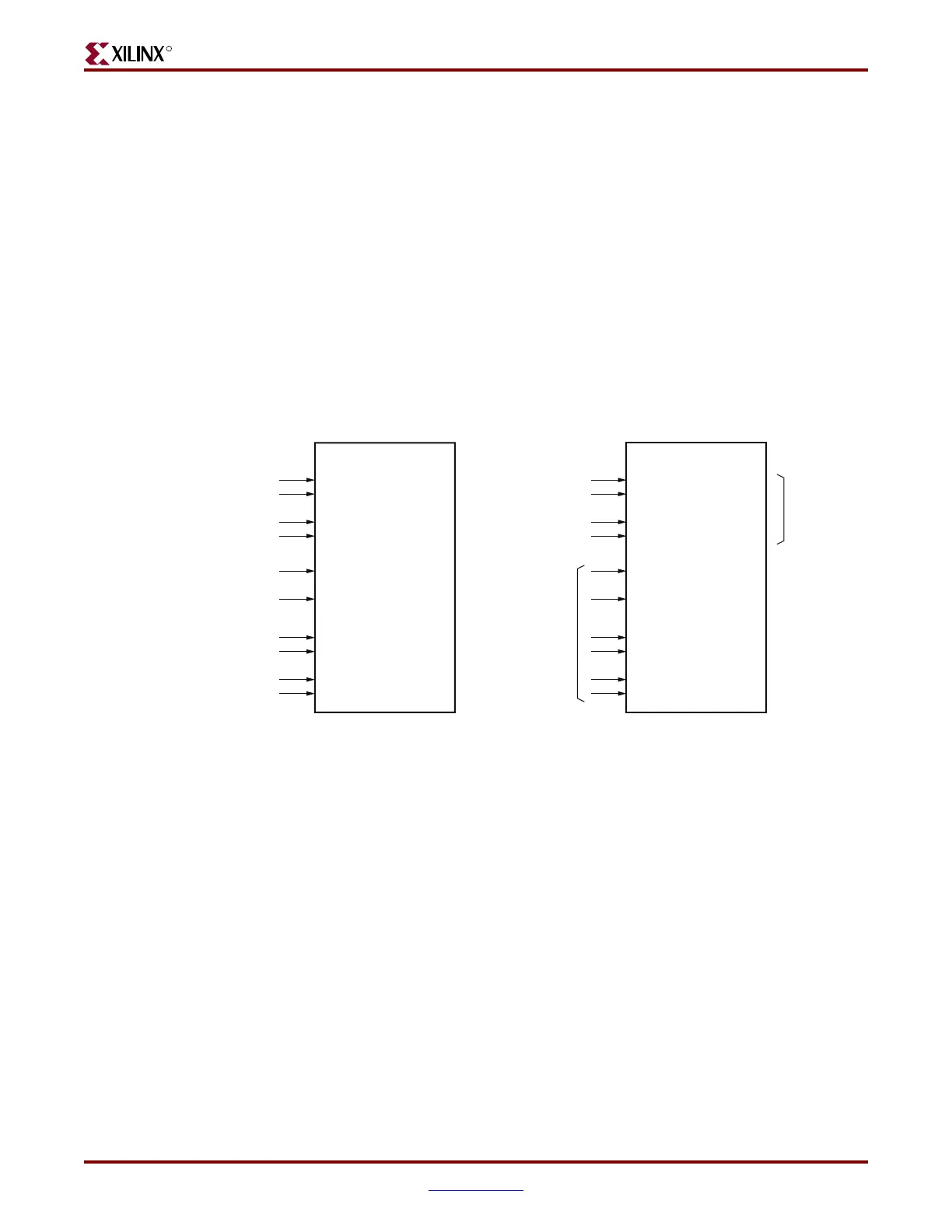
The example shown in Figure 5-10 shows the recommended method to power down an
unused tile or an unused transceiver in a tile.
Transition time in ns
CLK25_DIVIDER
CLKIN
-----------------------------------------------
⎝⎠
⎛⎞
TRANS_TIME attribute×=
Figure 5-10: Powering Down an Unused Tile
GTP_DUAL Tile
PLLPOWERDOWN
REFCLKPWRDNB
RXPOWERDOWN0[1]
RXPOWERDOWN0[0]
RXPOWERDOWN1[1]
RXPOWERDOWN1[0]
TXPOWERDOWN0[1]
TXPOWERDOWN0[0]
TXPOWERDOWN1[1]
TXPOWERDOWN1[0]
1
1
1
1
1
1
1
1
1
0
GTP_DUAL Tile
PLLPOWERDOWN
REFCLKPWRDNB
RXPOWERDOWN0[1]
RXPOWERDOWN0[0]
RXPOWERDOWN1[1]
RXPOWERDOWN1[0]
TXPOWERDOWN0[1]
TXPOWERDOWN0[0]
TXPO
WERDOWN1[1]
TXPOWERDOWN1[0]
1
1
1
1
Disabled
Transceiver
Controlled
by
Application
Disabled Tile Disabled Transceiver
UG196_c5_10_082906
 Loading...

