Virtex-5 RocketIO GTP Transceiver User Guide www.xilinx.com 261
UG196 (v1.3) May 25, 2007
Primary Differences
R
Flexibility
In Virtex-II Pro devices, changing of attributes requires partial reconfiguration. Virtex-4
and Virtex-5 devices allow all attribute changes from the DRP, and any default values can
be set in the HDL itself.
Board Guidelines
Power Supply Filtering
The Virtex-5 GTP transceivers simplify power supply design over previous generations in
two ways:
1. Only two supply voltages are needed to power the transceivers.
2. Because the two transceivers that share a tile have common power pins, the number of
power supply filtering components is reduced.
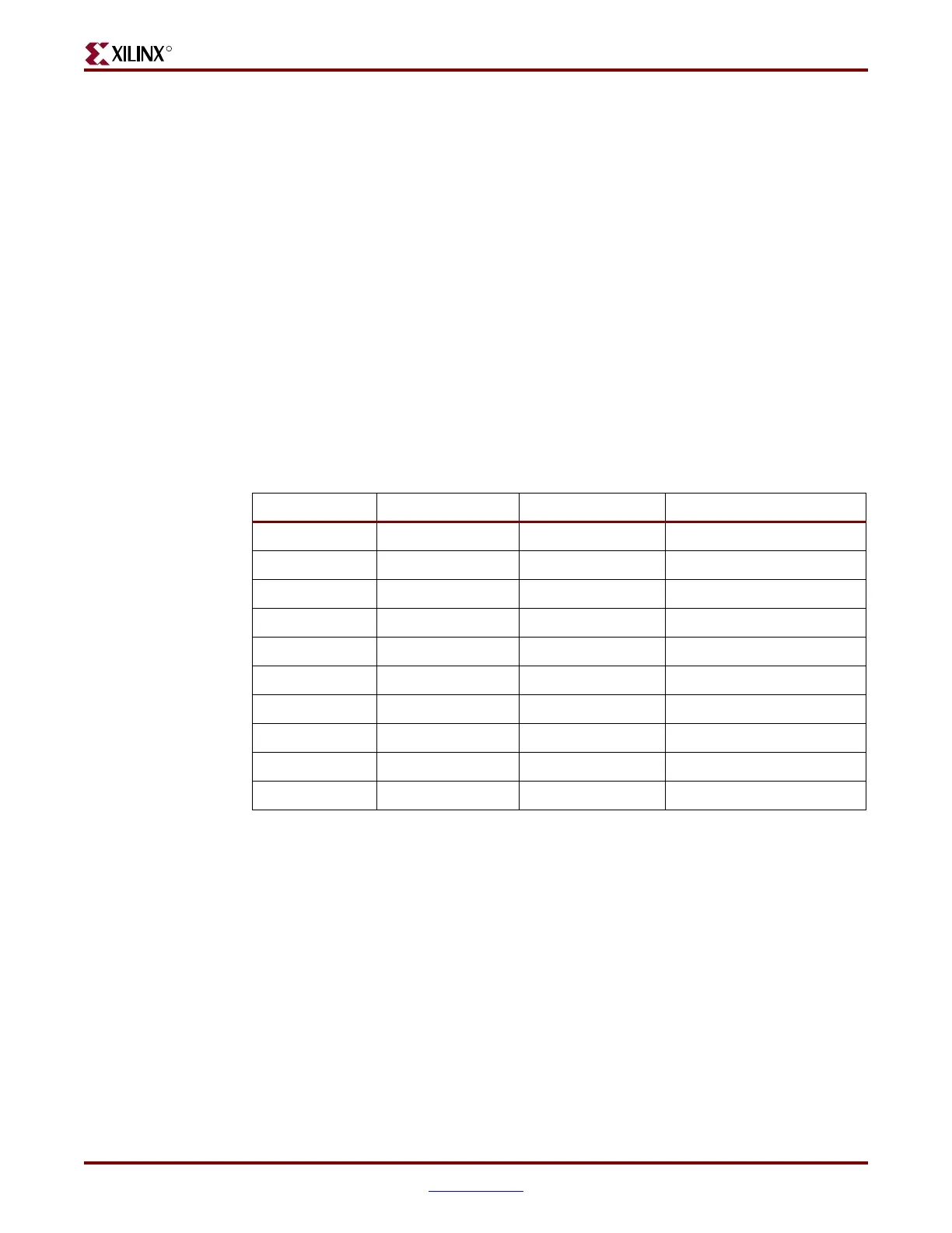
Table A-7 shows the power pin voltages for all Virtex families, and Figure A-3 shows the
power supply filtering for all Virtex families.
Tab le A - 7 : Power Pin Voltages
Pin Virtex-II Pro MGT Virtex-4 MGT Virtex-5 GTP Transceiver
(1)
AVCCAUXRX 2.5V 1.2V -
AVCCAUXTX 2.5V 1.2V -
AVCCAUXMGT N/A 2.5V -
VTTX 1.8 - 2.5V
(2)
1.5V -
VTRX 1.5 - 2.5V
(2)
0.25 - 2.5V
(2)
-
MGTAVCCPLL - - 1.2V
MGTAVCC - - 1.0V
MGTAVTTTX - - 1.2V
MGTAVTTRX - - 1.2V
MGTAVTTRXC - - 1.2V
Notes:
1. Nominal values. Refer to the device data sheets for values and operating conditions.
2. Depends on AC/DC coupling or termination options. See the device user guides for more details.
 Loading...

