196 www.xilinx.com Virtex-5 RocketIO GTP Transceiver User Guide
UG196 (v1.3) May 25, 2007
Chapter 9: Loopback
R
The LOOPBACK[2:0] port selects between the normal operation mode and the different
loopback modes.
Ports and Attributes
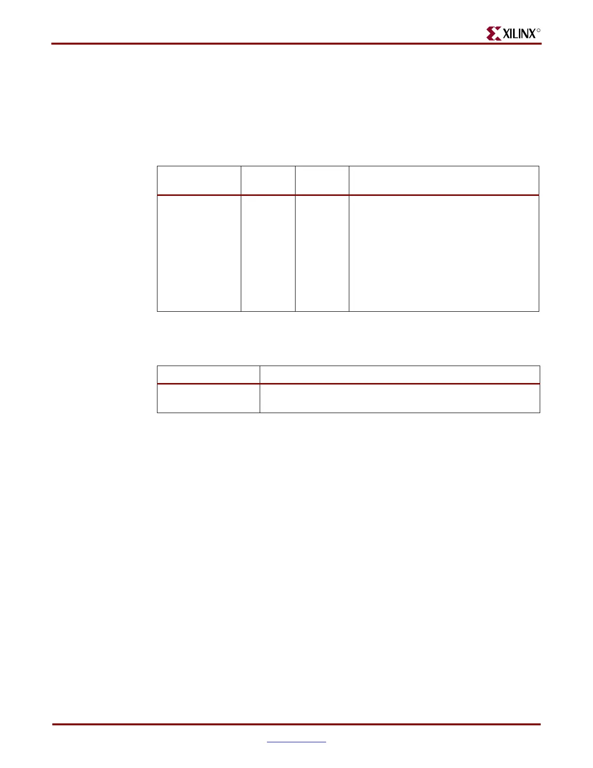
Table 9-1 defines the Loopback ports. Table 9-2 defines the attributes.
Description
Near-End PCS Loopback
The test data is generated and checked by user logic and then looped back in the PCS. The
difference compared to the Near-End PMA Loopback mode is that the PMA section is not
involved. The test data is looped back before passing the parallel-to-serial and the serial-to-
parallel converter. All analog high-speed circuits in the PMA section can be completely
powered down. Figure 9-2 illustrates this configuration.
Table 9-1: Loopback Ports
Port Dir
Clock
Domain
Description
LOOPBACK0[2:0]
LOOPBACK1[2:0]
In Async
000: Normal operation
001: Near-End PCS Loopback
010: Near-End PMA Loopback
011: Reserved
100: Far-End PMA Loopback
101: Reserved
110: Far-End PCS Loopback
(1)
111: Reserved
Notes:
1. PCI Express compliant.
Table 9-2: Loopback Attributes
Attribute Description
PMA_COM_CFG[89:0]
Common PMA configuration attribute. Leave at the default value
automatically set by the RocketIO GTP Transceiver Wizard.
 Loading...

