176 www.xilinx.com Virtex-5 RocketIO GTP Transceiver User Guide
UG196 (v1.3) May 25, 2007
Chapter 7: GTP Receiver (RX)
R
Ports and Attributes
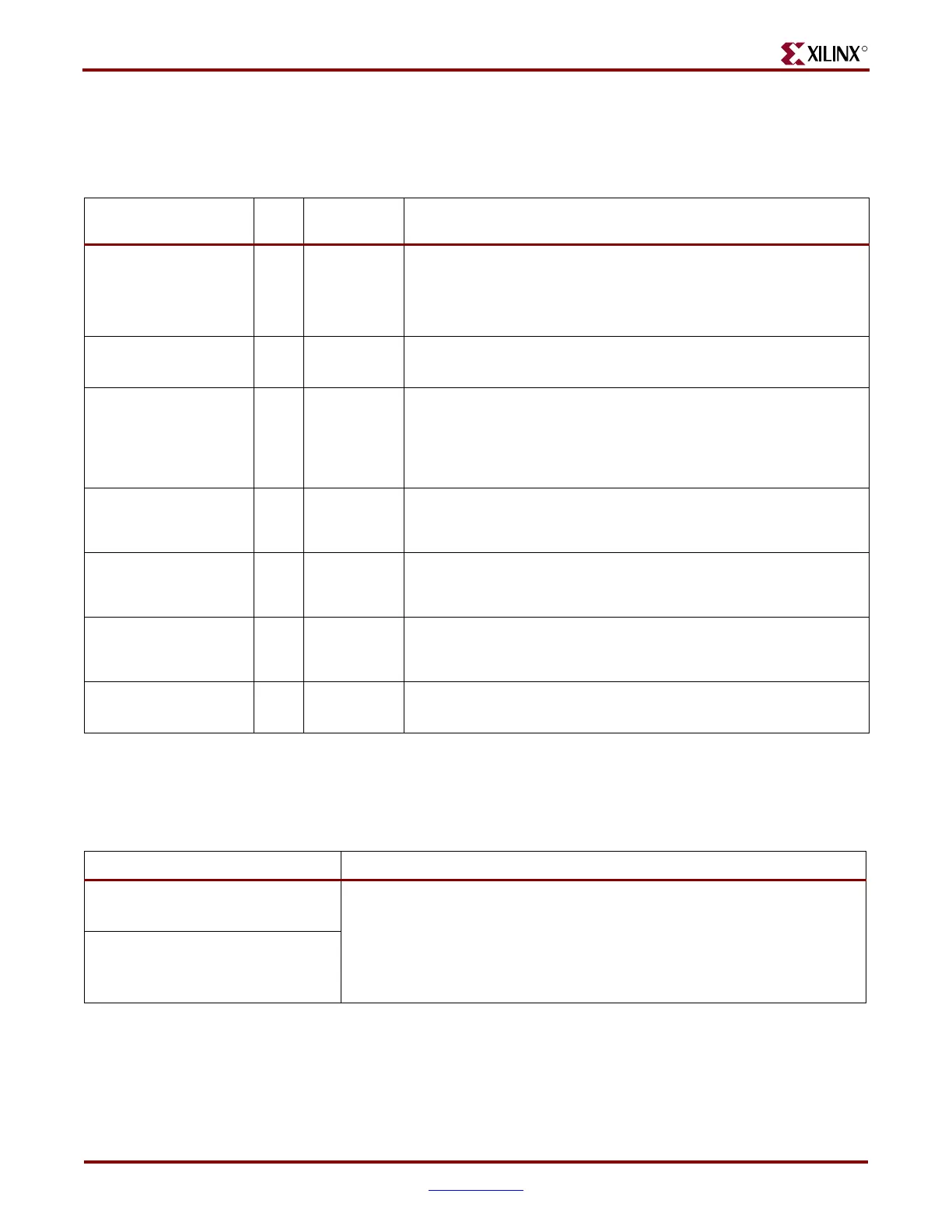
Table 7-32 defines the channel bonding ports.
Table 7-33 defines the channel bonding attributes.
Table 7-32: Channel Bonding Ports
Port Dir
Clock
Domain
Description
INTDATAWIDTH In Async
Specifies the bit width for the TX and RX internal datapaths. This port
controls both transceivers on the tile.
0: 8-bit width
1: 10-bit width
(1)
RXCHANBONDSEQ0
RXCHANBONDSEQ1
Out RXUSRCLK2
Goes High when RXDATA contains the start of a channel bonding
sequence.
RXCHANISALIGNED0
RXCHANISALIGNED1
Out RXUSRCLK2
FPGA signal from the elastic buffer. Stays High to indicate that the
channel is properly aligned with the master transceiver according to
observed channel bonding sequences in the data stream. Goes Low if
an unaligned channel bonding sequence is detected, indicating that
channel alignment was lost.
RXCHANREALIGN0
RXCHANREALIGN1
Out RXUSRCLK2
FPGA signal from the elastic buffer. Held High for at least one cycle
when the receiver has changed the alignment between this transceiver
and the master.
RXCHBONDI0[2:0]
RXCHBONDI1[2:0]
In RXUSRCLK
FPGA channel bonding control. Used only by slaves. Driven from
another transceiver's RXCHBONDO port that is the master in this
configuration.
RXCHBONDO0[2:0]
RXCHBONDO1[2:0]
Out RXUSRCLK
FPGA channel bonding control. Used by the master and slaves to pass
channel bonding and clock correction control to other transceivers'
RXCHBONDI ports.
RXENCHANSYNC0
RXENCHANSYNC1
In RXUSRCLK2
Enable channel bonding (from FPGA to the master). Tie this port High
for slaves.
Notes:
1. 10-bit internal data width is necessary when the RX buffer is bypassed or the PRBS generation/detection is used or both.
Table 7-33: Channel Bonding Attributes
Attribute Description
CHAN_BOND_1_MAX_SKEW_0
CHAN_BOND_1_MAX_SKEW_1
Control the number of USRCLK cycles that the master waits before ordering the
slaves to execute channel bonding. This attribute determines the maximum
skew that can be handled by channel bonding. It must always be less than the
minimum distance (in bytes or 10-bit codes) between channel bonding
sequences.
Valid values range from 1 to 14.
CHAN_BOND_2_MAX_SKEW_0
CHAN_BOND_2_MAX_SKEW_1
 Loading...

