50 www.xilinx.com Virtex-5 RocketIO GTP Transceiver User Guide
UG196 (v1.3) May 25, 2007
Chapter 4: Implementation
R
There are no attributes for this section.
Description
The position of GTP_DUAL tiles is specified by an XY coordinate system that describes the
column number and its relative position within that column. In current members of the
Virtex-5 LXT and SXT Platforms, all GTP_DUAL tiles are located in a single column along
one side of the die. As a result the X coordinate for all of the GTP_DUAL tiles is 0. “Package
Placement Information,” page 52 lists the GTP_DUAL tile position information for all
available device and package combinations along with the pad numbers for the external
signals associated with each tile.
There are two ways to create a UCF for designs that utilize GTP_DUAL tiles. The preferred
method is by using the RocketIO GTP Wizard. The Wizard (see Chapter 2, “RocketIO GTP
Transceiver Wizard”) automatically generates UCF templates that configure the
transceivers and contain placeholders for GTP_DUAL placement information. The UCFs
generated by the Wizard can then be edited to customize operating parameters and
placement information for the application.
The second approach is to create the UCF by hand. When using this approach, the designer
must enter both configuration attributes that control transceiver operation as well as tile
location parameters. Care must be taken to ensure that all of the parameters needed to
configure the GTP_DUAL tile are correctly entered.
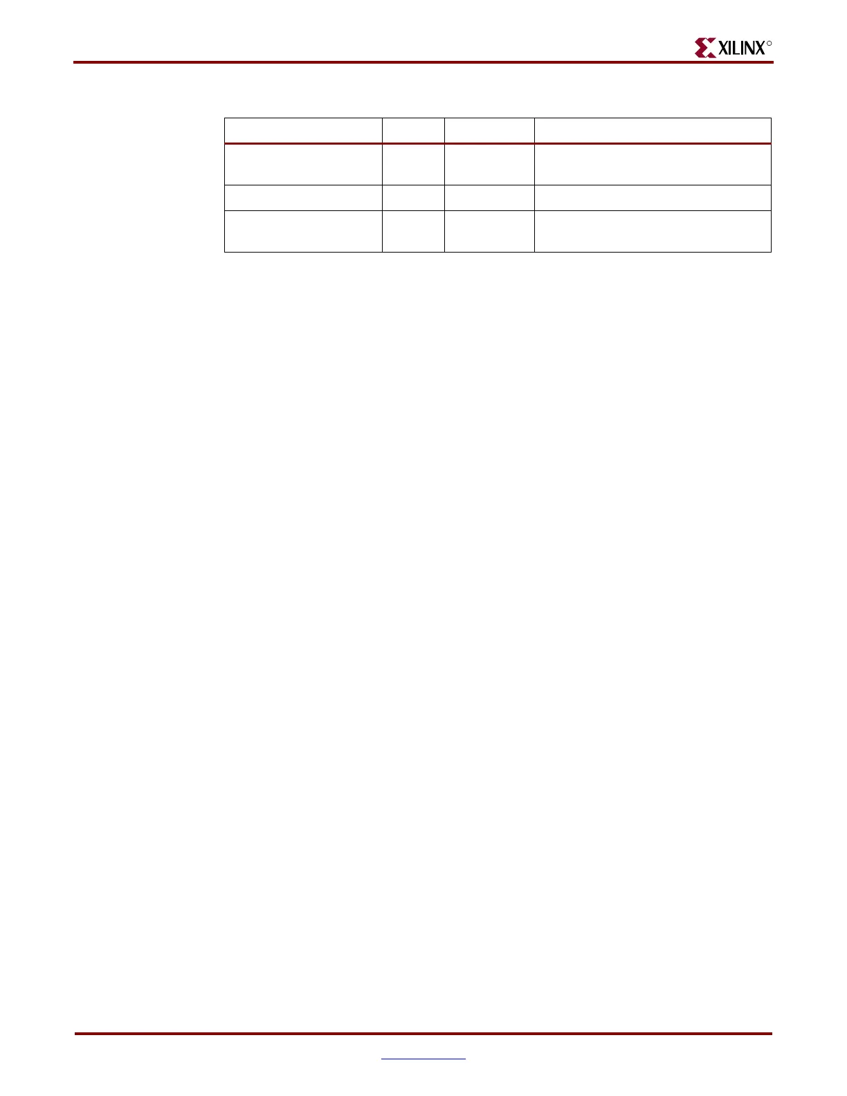
MGTAVCC
(2)
Analog Analog
Two pads for 1.0V supply for
transceiver mixed signal circuitry
MGTAVTTRX
(2)
Analog Analog Pad for 1.2V supply for RX circuitry
MGTAVTTTX
(2)
Analog Analog
Two pads for 1.2V supply for TX
circuitry
Notes:
1. These port names have the prefix MGT to identify them easily in a pad file that is very often used to
create symbols for board design schematics. In this document, the MGT prefix was removed from
those names; however, names with and without the MGT prefix are synonymous to each other.
2. Nominal values. Refer to DS202: Virtex-5 Data Sheet for exact values and marginal conditions.
Table 4-1: GTP_DUAL Tile External Ports (Continued)
Port Dir Domain Description
 Loading...

