POWR
5-35
6F65G11
Power unit
NOTE:
If any of the measurements are out of speci-
fication, reassemble the crankshaft.
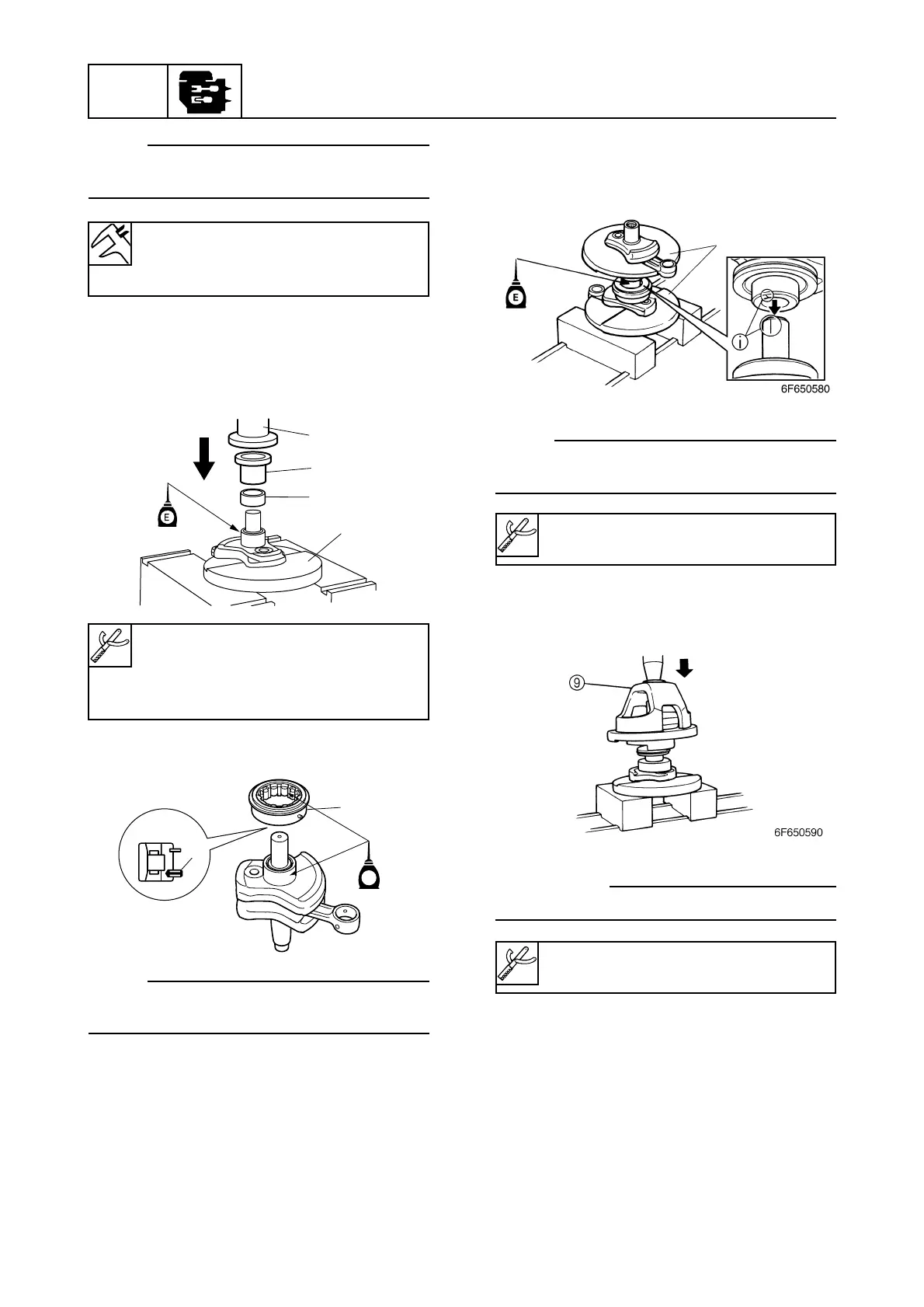
13. Install the inner race 0 onto crank 2 by
using a press and the bushing 3.
Carefully press the inner race onto the
shaft.
14. Install the roller bearing e onto crank 2.
NOTE:
Make sure the pin h side of the bearing
faces crank 2.
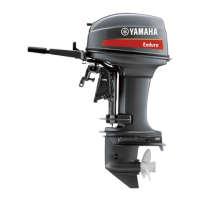
15. Insert plate C q between crank 1 and
crank 2, and install the labyrinth ring on
crank 3, before connecting crankshaft
assemblies 3 and 4.
16. Insert plate C q between crank 3 and
crank 4, then place them onto the crank-
shaft assemblies 1 and 2.
NOTE:
Align the alignment marks i on cranks 2 and
3.
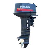
17. Place the press body 9 on plate C and
install the crank 2 into crank 3 using a
press.
cC
Do not apply force in excess of 7 tons.