6F65G11
5-34
9
8
7
6
5
4
3
2
1
Crankcase
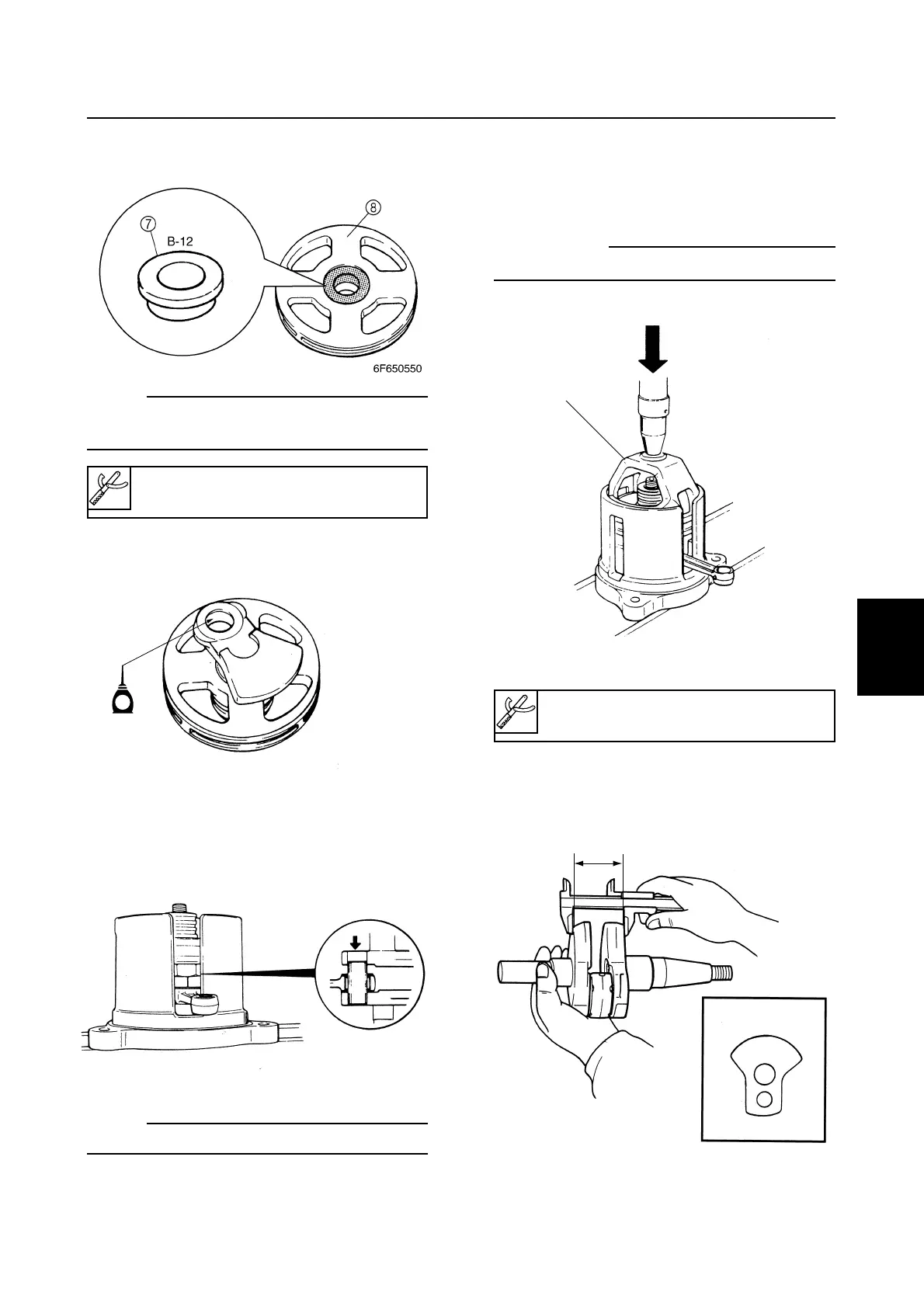
8. Install the bushing 7 on the pressure
plate 8.
NOTE:
When installing crank 3 to the pressure plate,
do not use the bushing 7.
9. Install crank 1 (or crank 3) to the pres-
sure plate.
10. Align the crankpin hole in crank 1 (or
crank 3) with the crankpin fitted to crank
2 (or crank 4) and place the pressure
plate in the body.
NOTE:
Apply engine oil to the crankpin.
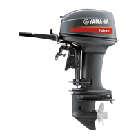
11. Insert the press body 9, and install crank
1 (or crank 3) onto the crankpin using a
press.
cC
Do not apply force in excess of 5 tons.
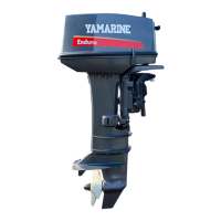
12. Measure the width b of the assembled
crankshaft using calipers. Measurements
should be made at positions c to g.
Bushing-12 (D35) 7: 90890-02366
Pressure plate 8: 90890-02384
Press body 9: 90890-02385