3-6
PERIODIC MAINTENANCE
• Front side panel
Refer to “GENERAL CHASSIS (1)” on
page 4-1.
• Radiator
Refer to “RADIATOR” on page 6-3.
2. Remove:
• Ignition coil
• Spark plug
• Cylinder head cover
• Cylinder head cover gasket
Refer to “CAMSHAFTS” on page 5-16.
3. Remove:
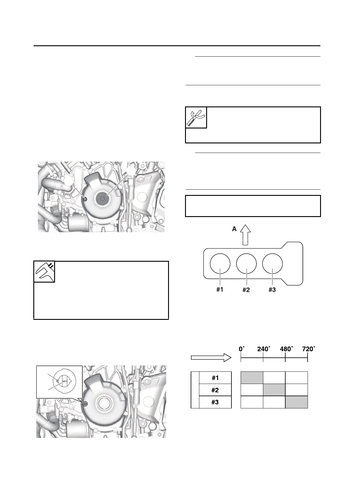
• Timing mark accessing bolt “1”
• Crankshaft end cover “2”
4. Measure:
• Valve clearance
Out of specification → Adjust.
a. Turn the crankshaft counterclockwise.
b. When piston #1 is at TDC on the compres-
sion stroke, align the TDC mark “a” on the
generator rotor with the generator rotor cov-
er mark “b”.
TDC on the compression stroke can be found
when the camshaft lobes are turned away from
each other.
c. Measure the valve clearance with a thick-
ness gauge.
• If the valve clearance is incorrect, record the
measured reading.
• Measure the valve clearance in the following
sequence.
d. To measure the valve clearances of the
other cylinders, starting with cylinder #1 at
TDC, turn the crankshaft counterclockwise
as specified in the following table.
Valve clearance (cold)
Intake
0.11–0.20 mm (0.0043–0.0079
in)
Exhaust
0.28–0.32 mm (0.0110–0.0126
in)
Thickness gauge
90890-03268
Feeler gauge set
YU-26900-9
Valve clearance measuring sequence
Cylinder #1 → #2 → #3
A. Front
B. Degrees that the crankshaft is turned coun-
terclockwise
C. Cylinder
D. Combustion cycle